REAR DIFFERENTIAL CARRIER ASSEMBLY > REASSEMBLY |
| 1. ASSEMBLE DIFFERENTIAL CASE (for 2 Pinion Gear Type) |
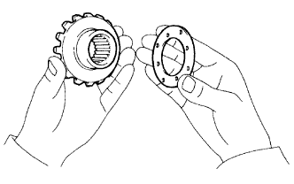 |
Install the side gear thrust washer to the side gear.
| Thickness mm (in.) | Thickness mm (in.) |
| 1.48 to 1.52 (0.058 to 0.060) | 1.73 to 1.77 (0.068 to 0.070) |
| 1.53 to 1.57 (0.060 to 0.062) | 1.78 to 1.82 (0.070 to 0.072) |
| 1.58 to 1.62 (0.062 to 0.064) | 1.83 to 1.87 (0.072 to 0.074) |
| 1.63 to 1.67 (0.064 to 0.066) | 1.88 to1. 92 (0.074 to 0.076) |
| 1.68 to 1.72 (0.066 to 0.068) | - |
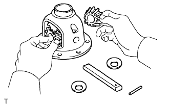 |
Install 2 side gears, 2 pinion gears, 2 side gear thrust washers, 2 pinion gears, 2 pinion thrust washers and the pinion shaft in the differential case.
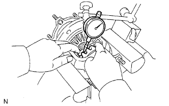 |
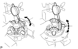
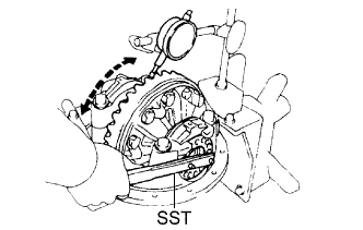
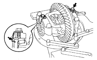
Measure the side gear backlash.
Using a dial indicator, measure the side gear backlash while holding one pinion gear toward the differential case.
 |
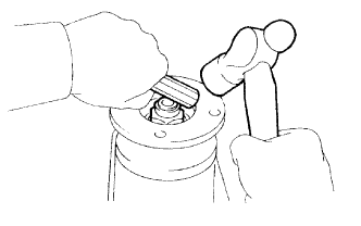
Using a pin punch and hammer, tap in the straight pin through the differential case and hole of the pinion shaft.
Stake the differential case.
| 2. ASSEMBLE DIFFERENTIAL CASE (for LSD) |
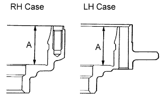 |
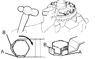
Measure the differential case dimension labeled A.
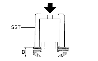 |
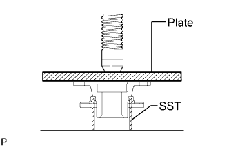
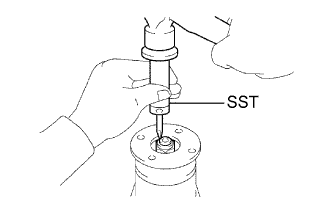
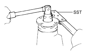
Install the side gear thrust washers No. 1 and clutch plate to the side gear.
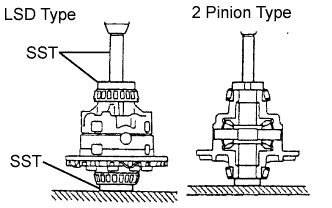
While using SST to press the washers and plates with a pressure of 10 kgf (22 lbf), measure the dimension B.
Calculate the thickness of the new washer using the formula below.
| Thickness mm (in.) | Identifying Mark |
| 1.83 to 1.89 (0.072 to 0.074) | B |
| 1.89 to 1.95 (0.074 to 0.077) | C |
| 1.95 to 2.01 (0.077 to 0.079) | D |
| 2.01 to 2.07 (0.079 to 0.081) | E |
| 2.07 to 2.13 (0.081 to 0.084) | F |
| 2.13 to 2.19 (0.084 to 0.086) | G |
| 2.19 to 2.25 (0.086 to 0.089) | H |
| 2.25 to 2.31 (0.089 to 0.091) | J |
| 2.31 to 2.37 (0.091 to 0.093) | K |
| 2.37 to 2.43 (0.093 to 0.096) | L |
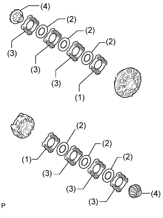 |
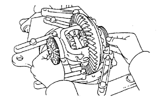
Install the following parts to the differential cases.
 |
Install the 4 pinion gears and thrust washers to the spider.
Align the spring RH retainer holes with the spider knock pins and install the RH retainer.
Install the pinion gears and spider to the differential RH case.
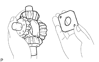
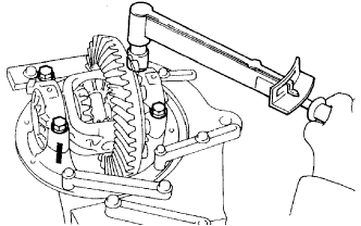
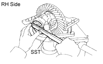
Using a dial indicator, measure the side gear backlash while holding the side gear spider.
 |
Reinstall the spider to the RH case tightly and do not move the spring retainer.
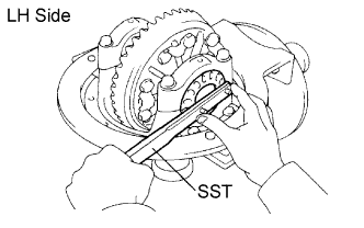
Install the compression spring and spring LH retainer.
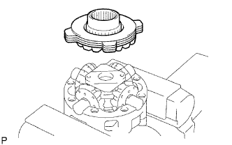 |
Install the side gear, thrust washers and clutch plates.
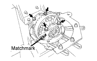
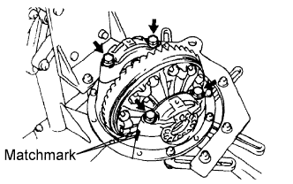
Align the matchmarks and assemble the RH and LH cases.
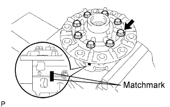 |
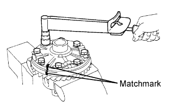
Align the matchmarks on the differential case RH and differential case LH.
Install the 8 bolts by diametrically tightening the bolts uniformly in several passes.
| 3. INSTALL DIFFERENTIAL RING GEAR |
 |
Clean the contact surfaces of the differential case and ring gear.
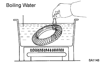
Heat the ring gear in boiling water that is approximately 100°C (212°F).
Carefully remove the ring gear from the boiling water.
After the moisture on the ring gear has completely evaporated, quickly install the ring gear to the differential case.
 |
Align the matchmarks on the ring gear with those of the differential case.
Temporarily install 5 new lock plates and 10 bolts.
After the ring gear cools down, install the 8 bolts by diametrically tightening the bolts uniformly in several passes.
 |
Using a chisel and hammer, stake the 5 lock plates.
| 4. INSTALL REAR DIFFERENTIAL CASE BEARING |
 |
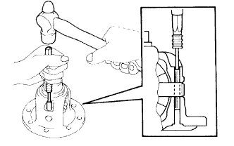
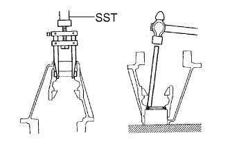
Using SST and a press, press the bearing onto the differential case.
| 5. INSPECT DIFFERENTIAL RING GEAR RUNOUT |
 |
Install the differential case on the carrier, and install the 2 adjusting nuts so that there is no play in the bearing.
Install the 2 bearing caps with the 4 bolts.
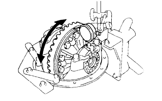
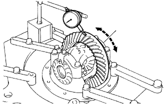
Using a dial indicator, measure the runout of the ring gear.
Remove the 2 bearing caps, 2 adjusting nuts and differential case.
| 6. INSTALL REAR DIFFERENTIAL DUST DEFLECTOR |
 |
Using SST, a plate and a press, press in the dust deflector.
| 7. INSTALL REAR DRIVE PINION FRONT TAPERED ROLLER BEARING |
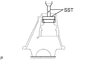 |
Using a brass bar and hammer, tap in the oil storage ring.
Using SST and a press, press the roller bearing (outer) to the carrier.
| 8. INSTALL REAR DRIVE PINION REAR TAPERED ROLLER BEARING |
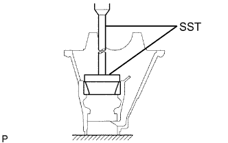 |
Using SST and a press, press the roller bearing (outer) into the carrier.
| 9. INSTALL REAR DRIVE PINION REAR TAPERED ROLLER BEARING |
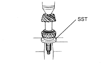 |
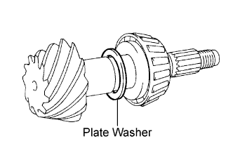
Install the plate washer on the drive pinion.
Using SST and a press, press the roller bearing (inner) onto the drive pinion.
| 10. ADJUST DIFFERENTIAL DRIVE PINION PRELOAD |
 |
Install the drive pinion, rear drive pinion tapered roller bearing and rear differential drive oil slinger.
 |
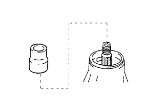
Using SST, install the companion flange.
 |
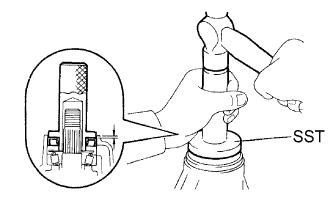
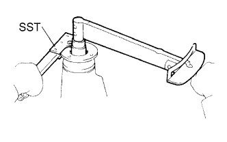
Adjust the drive pinion preload by tightening the companion flange nut.
Using SST to hold the companion flange in place, torque the nut.
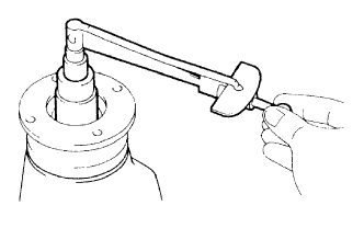
Using a torque wrench, measure the preload.
| Bearing | Preload |
| New bearing | 1.05 to 1.64 N*m (10.7 to 16.7 kgf*cm, 9.3 to 14.5 in.*lbf) |
| Reused bearing | 0.56 to 0.85 N*m (5.7 to 8.7 kgf*cm, 4.9 to 7.5 in.*lbf) |
| 11. INSTALL DIFFERENTIAL CASE ASSEMBLY |
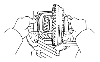 |
Place the 2 bearing outer races on their respective bearings.
| 12. INSTALL REAR DIFFERENTIAL BEARING ADJUSTING NUT |
 |
Install the 2 adjusting nuts on the carrier, making sure the nuts are threaded properly.
| 13. INSPECT AND ADJUST BACKLASH DIFFERENTIAL RING GEAR AND DIFFERENTIAL DRIVE PINION |
 |
Align the matchmarks on the cap and carrier.
 |
Install the right and left bearing caps with the 4 bolts.
 |
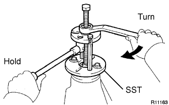
Loosen the 4 bearing cap bolts to the point where the adjusting nuts can be turned by SST.
Using SST, torque the adjusting nut on the ring gear side until the ring has a backlash of about 0.2 mm (0.008 in.).
 |
While turning the ring gear, use SST to fully tighten the adjusting nut on the drive pinion side. After the bearings have settled, loosen the adjusting nut on the drive pinion side.
Using SST, tighten the adjusting nut 1 to 1.5 notches from the 0 preload position.
 |
Using a dial indicator, adjust the ring gear backlash until it is within the specification.
 |
Torque the bearing cap bolts.
| 14. INSPECT TOTAL PRELOAD |
Using a torque wrench, measure the preload with the teeth of the drive pinion and ring gear in contact.
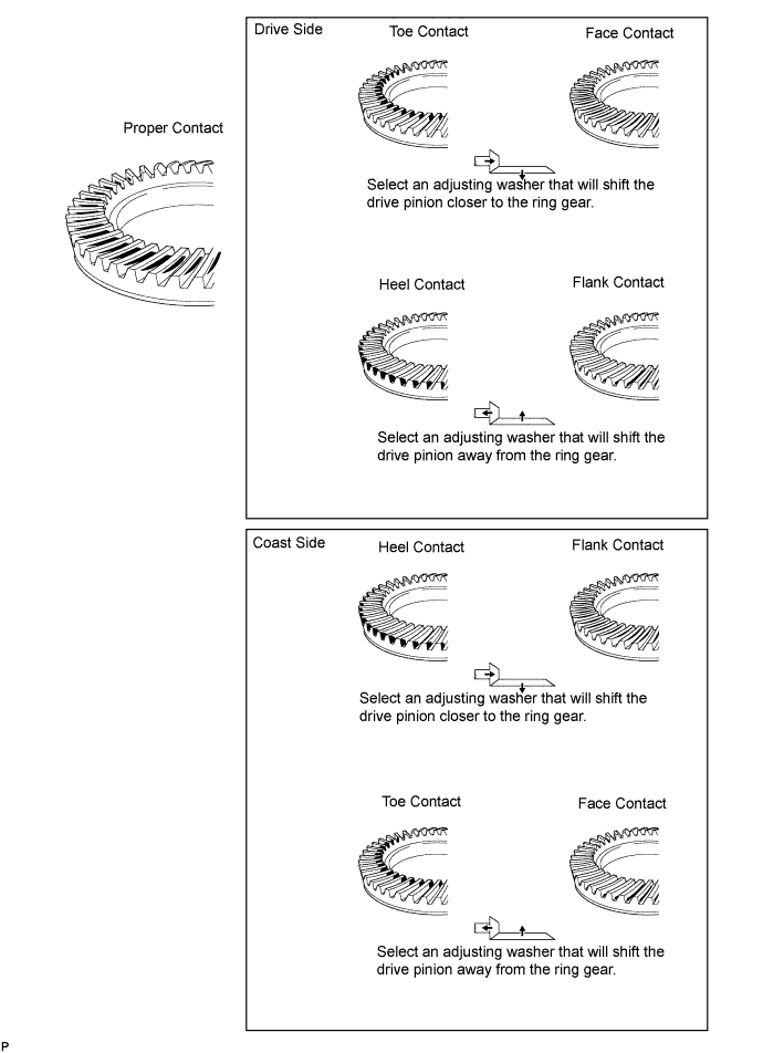
| 15. INSPECT TOOTH CONTACT BETWEEN RING GEAR AND DRIVE PINION |
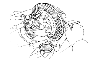 |
Coat 3 or 4 teeth at 3 different positions on the ring gear with red lead primer.
Hold the companion flange firmly in place and rotate the ring gear in both directions.
Inspect the tooth contact pattern.
| Thickness mm (in.) | Thickness mm (in.) |
| 1.69 to 1.71 (0.0665 to 0.0673) | 2.02 to 2.04 (0.0795 to 0.0803) |
| 1.72 to 1.74 (0.0677 to 0.0685) | 2.05 to 2.07 (0.0807 to 0.0815) |
| 1.75 to 1.77 (0.0689 to 0.0697) | 2.08 to 2.10 (0.0819 to 0.0827) |
| 1.78 to 1.80 (0.0701 to 0.0709) | 2.11 to 2.13 (0.0831 to 0.0839) |
| 1.81 to 1.83 (0.0713 to 0.0720) | 2.14 to 2.16(0.0843 to 0.0850) |
| 1.84 to 1.86 (0.0724 to 0.0732) | 2.17 to 2.19 (0.0854 to 0.0862) |
| 1.87 to 1.89 (0.0736 to 0.0744) | 2.20to 2.22 (0.0866 to 0.0874) |
| 1.90 to 1.92 (0.0748 to 0.0756) | 2.23 to 2.25 (0.0878 to 0.0886) |
| 1.93 to 1.95 (0.0760 to 0.0768) | 2.26 to 2.28 (0.0890 to 0.0898) |
| 1.96 to 1.98 (0.0772 to 0.0780) | 2.29 to 2.31 (0.0902 to 0.0909) |
| 1.99 to 2.01 (0.0783 to 0.0791) | 2.32 to 2.34 (0.0913 to 0.0921) |
| 16. REMOVE REAR DRIVE PINION NUT |
 |
Using SST and a hammer, loosen the staked part of the nut.
 |
Using SST to hold the companion flange in place, remove the nut.
| 17. REMOVE REAR DRIVE PINION COMPANION FLANGE SUB-ASSEMBLY |
| 18. REMOVE REAR DIFFERENTIAL DRIVE PINION OIL SLINGER |
| 19. REMOVE REAR DRIVE PINION FRONT TAPERED ROLLER BEARING |
 |
Using SST, remove the roller bearing (outer) from the carrier.
Using a brass bar and hammer, tap out the oil storage ring from the carrier.
| 20. INSTALL REAR DIFFERENTIAL DRIVE PINION BEARING SPACER |
 |
Install a new bearing spacer to the drive pinion.
| 21. INSTALL REAR DRIVE PINION FRONT TAPERED ROLLER BEARING |
|
| 22. INSTALL REAR DIFFERENTIAL DRIVE PINION OIL SLINGER |
| 23. INSTALL REAR DIFFERENTIAL CARRIER OIL SEAL |
 |
Apply MP grease to a new oil seal.
Using SST and a hammer, tap in the oil seal.
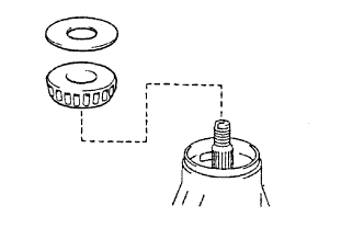
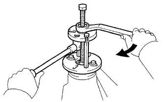
| 24. INSTALL REAR DRIVE PINION COMPANION FLANGE SUB-ASSEMBLY |
 |
Using SST, install the companion flange on the drive pinion.
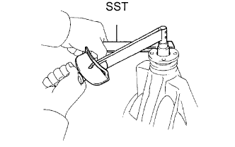
 |
Coat the threads of a new nut with hypoid gear oil LSD.
Using SST to hold the flange, torque the nut.
| 25. INSPECT DRIVE PINION PRELOAD |
 |
Using a torque wrench, measure the preload of the backlash between the drive pinion and ring gear.
| Bearing | Preload |
| New bearing | 1.05 to 1.64 N*m (11 to 17 kgf*cm, 9.3 to 15 in.*lbf) |
| Reused bearing | 0.56 to 0.85 N*m (6 to 9 kgf*cm, 4.9 to 7.5 in.*lbf) |
| 26. INSPECT TOTAL PRELOAD |
|
Using a torque wrench, measure the preload.
| 27. INSPECT DIFFERENTIAL RING GEAR BACKLASH |
 |
Using a dial indicator, check the backlash of the ring gear.
| 28. INSPECT RUNOUT OF REAR DRIVE PINION COMPANION FLANGE SUB-ASSEMBLY |
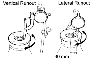 |
Using a dial indicator, measure the runout of the drive pinion companion flange vertically and laterally.
| Runout | Maximum |
| Vertical runout | 0.10 mm (0.0039 in.) |
| Lateral runout | 0.10 mm (0.0039 in.) |
| 29. STAKE DRIVE PINION NUT |
 |
Using a chisel and hammer, stake the nut.
| 30. INSTALL REAR DIFFERENTIAL BEARING ADJUSTING NUT LOCK |
 |
Install 2 new adjusting locks on the bearing caps with the 2 bolts.
Bend the nut locks.
