FRONT DIFFERENTIAL CARRIER ASSEMBLY > REASSEMBLY |
| 1. INSTALL FRONT DIFFERENTIAL SIDE GEAR SHAFT RH BEARING |
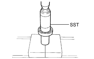 |
Using SST and a press, press in a new shaft bearing.
Using a snap ring expander, install the snap ring.
| 2. INSTALL DIFFERENTIAL SIDE GEAR SHAFT SUB-ASSEMBLY RH |
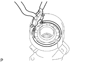 |
Install the shaft into the differential tube.
Using needle nose pliers, install the snap ring.
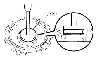
| 3. INSTALL DIFFERENTIAL SIDE GEAR SHAFT OIL SEAL |
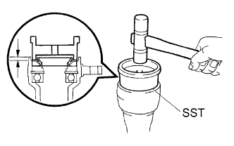 |
Coat the lip of the new oil seal with MP grease.
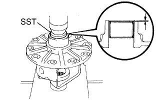
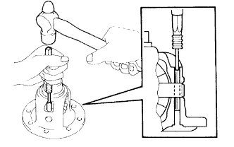
Using SST and a plastic-faced hammer, tap in the oil seal.
| 4. INSTALL DIFFERENTIAL CLUTCH HUB |
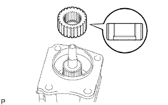 |
Install the clutch hub to the side gear inter shaft.
Using snap ring pliers, install the snap ring.
| 5. INSTALL FRONT DIFFERENTIAL SIDE GEAR NEEDLE ROLLER BEARING |
 |
Using SST and a press, press in 2 new bearings.
| 6. ASSEMBLE DIFFERENTIAL CASE |
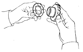 |
Install 2 thrust washers on the 2 side gears.
| Thickness mm (in.) | Thickness mm (in.) |
| 1.48 to 1.52 (0.0583 to 0.0598) | 1.73 to 1.77 (0.0681 to 0.0697) |
| 1.53 to 1.57 (0.0602 to 0.0618) | 1.78 to 1.82 (0.0701 to 0.0717) |
| 1.58 to 1.62 (0.0622 to 0.0638) | 1.83 to 1.87 (0.0720 to 0.0736) |
| 1.63 to 1.67 (0.0642 to 0.0657) | 1.88 to 1.92 (0.0740 to 0.0756) |
| 1.68 to 1.72 (0.0661 to 0.0677) | - |
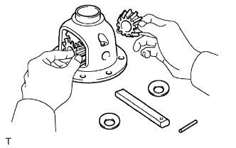 |
Install the 2 side gears, 2 pinion gears, 2 side gear thrust washers, 2 pinion thrust washers and pinion shaft in the differential case.
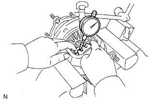 |
Measure the side gear backlash.
Using a dial indicator, measure the side gear backlash while holding one pinion gear toward the differential case.
 |
Using a pin punch and hammer, tap in the straight pin through the differential case and hole of the pinion shaft.
Stake the differential case.
| 7. INSTALL DIFFERENTIAL RING GEAR |
 |
Clean the contact surface of the differential case and ring gear.
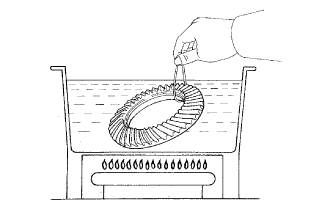
Heat the ring gear in boiling water that is approximately 100°C (212°F).
Carefully remove the ring gear from the boiling water.
After the moisture on the ring gear has completely evaporated, quickly install the ring gear to the differential case.
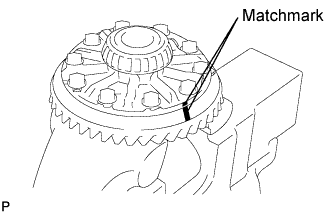 |
Align the matchmarks on the ring gear with those of the differential case.
After the ring gear cools down, apply thread lock adhesive to the 10 set bolts and install them.
| 8. INSTALL FRONT DIFFERENTIAL CASE BEARING |
 |
Using SST and a press, press in the bearing on the differential case.
| 9. INSTALL FRONT DIFFERENTIAL CASE BEARING |
 |
Using SST and a press, press in the case bearing (outer race) to the differential case bearing retainer.
 |
Using SST and a press, press in the case bearing (outer) to the differential carrier.
| 10. INSTALL BEARING OUTER RACE |
 |
Using SST, install the outer race front.
Using a brass bar and hammer, tap in the oil storage ring.
Using SST, install the outer race rear.
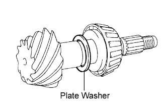
| 11. INSTALL FRONT DRIVE PINION FRONT TAPERED ROLLER BEARING |
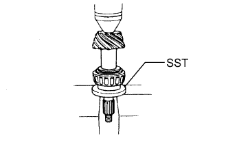 |
Install the washer on the drive pinion.
Using SST and a press, press the front bearing onto the drive pinion.
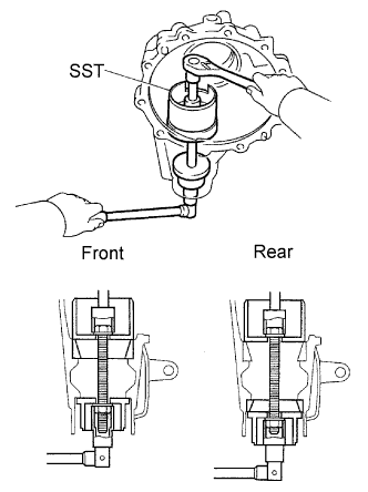
| 12. ADJUST DIFFERENTIAL DRIVE PINION PRELOAD |
 |
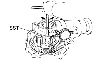
Install the drive pinion and oil slinger.
 |
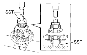
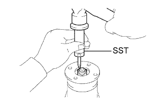
Using SST, install the companion flange.
 |
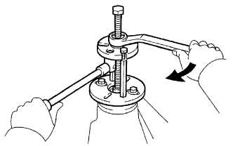
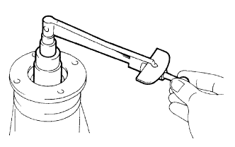
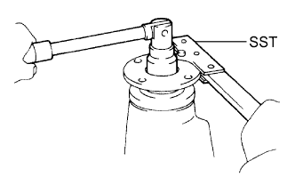
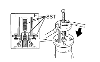
Adjust the drive pinion preload by tightening the companion flange nut.
Using SST to hold the flange in place, tighten the nut.
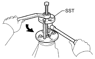
 |
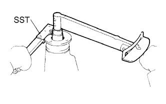
Using a torque wrench, measure the preload.
| Item | Specified Condition |
| New bearing | 0.98 to 1.57 N*m (5 to 8 kgf*cm, 4.3 to 6.9 in.*lbf) |
| Reused bearing | 0.49 to 0.78 N*m (5 to 8 kgf*cm, 4.3 to 6.9 in.*lbf) |
| 13. INSTALL DIFFERENTIAL CASE ASSEMBLY |
| 14. ADJUST BACKLASH DIFFERENTIAL RING GEAR AND DIFFERENTIAL DRIVE PINION |
Install the side bearing retainer with the 10 bolts.
 |
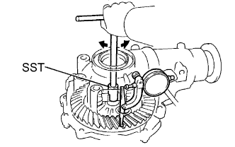
Using SST and a dial indicator, measure the ring gear backlash.
| Thickness mm (in.) | Thickness mm (in.) | Thickness mm (in.) |
| 1.57 to 1.59 (0.0618 to 0.0626) | 1.75 to 1.77 (0.0689 to 0.0697) | 2.03 to 2.05 (0.0791 to 0.0807) |
| 1.59 to 1.61 (0.0626 to 0.0634) | 1.77 to 1.79 (0.0697 to 0.0705) | 2.05 to 2.07 (0.0807 to 0.0815) |
| 1.61 to 1.63 (0.0634 to 0.0642) | 1.79 to 1.81 (0.0705 to 0.0713) | 2.07 to 2.09 (0.0815 to 0.0822) |
| 1.63 to 1.65 (0.0642 to 0.0650) | 1.81 to 1.83 (0.0713 to 0.0720) | 2.09 to 2.11 (0.0822 to 0.0830) |
| 1.65 to 1.67 (0.0650 to 0.0657) | 1.83 to 1.85 (0.0720 to 0.0728) | 2.11 to 2.13 (0.0830 to 0.0839) |
| 1.67 to 1.69 (0.0657 to 0.0665) | 1.85 to 1.87 (0.0728 to 0.0736) | 2.13 to 2.15 (0.0839 to 0.0846) |
| 1.69 to 1.71 (0.0665 to 0.0673) | 1.87 to 1.89 (0.0736 to 0.0744) | 2.15 to 2.17 (0.0846 to 0.0854) |
| 1.71 to 1.73 (0.0673 to 0.0681) | 1.89 to 2.01 (0.0744 to 0.0791) | - |
| 1.73 to 1.75 (0.0681 to 0.0689) | 2.01 to 2.03 (0.0791 to 0.0799) | - |
| 15. INSPECT TOTAL PRELOAD |
 |
Using a torque wrench, measure the preload with the teeth of the drive pinion and ring gear in contact.
| 16. ADJUST TOOTH CONTACT BETWEEN RING GEAR AND DRIVE PINION |
Remove the differential case bearing retainer and differential case.
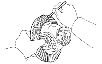 |
Coat 3 or 4 teeth at 3 different positions on the ring gear with red lead primer.
Install the differential case and differential case bearing retainer.
Hold the companion flange firmly in place and rotate the ring gear in both directions.
Remove the differential case bearing retainer and differential case.
Inspect the tooth contact pattern.
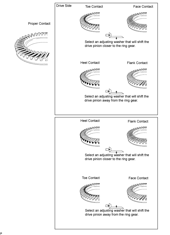
 |
If the teeth are not contacting properly, use the following chart to select a proper washer.
| Thickness mm (in.) | Thickness mm (in.) | Thickness mm (in.) |
| 1.69 to 1,71 (0.0665 to 0.0673) | 1.93 to 1,95 (0.0760 to 0.0768) | 2.17 to 2.19 (0.0854 to 0.0862) |
| 1.72 to 1,74 (0.0677 to 0.0685) | 1.96 to 1,98 (0.0772 to 0.0780) | 2.20 to 2.22 (0.0866 to 0.0874) |
| 1.75 to 1,77 (0.0689 to 0.0697) | 1.99 to 2.01 (0.0783 to 0.0791) | 2.23 to 2.25 (0.0878 to 0.0886) |
| 1.78 to 1,80 (0.0700 to 0.0709) | 2.02 to 2.04 (0.0795 to 0.0803) | 2.26 to 2.28 (0.0890 to 0.0898) |
| 1.81 to 1,83 (0.0713 to 0.0720) | 2.05 to 2.07 (0.0807 to 0.0815) | 2.29 to 2.31 (0.0902 to 0.0909) |
| 1.84 to 1,86 (0.0724 to 0.0732) | 2.08 to 2.10 (0.0819 to 0.0827) | 2.32 to 2.34 (0.0913 to 0.0921) |
| 1.87 to 1,89 (0.0736 to 0.0744) | 2.11 to 2.13 (0.0831 to 0.0839) | - |
| 1.90 to 1,92 (0.0748 to 0.0756) | 2.14 to 2.16 (0.0843 to 0.0850) | - |
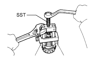
| 17. REMOVE FRONT DRIVE PINION COMPANION FLANGE NUT |
 |
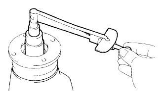
Using SST and a hammer, loosen the staked part of the nut.
 |
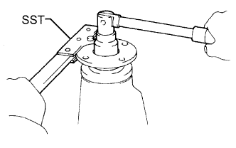
Using SST to hold the companion flange in place, remove the nut.
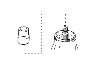
| 18. REMOVE FRONT DRIVE PINION COMPANION FLANGE SUB-ASSEMBLY |
 |
Using SST, remove the companion flange.
| 19. REMOVE FRONT DIFFERENTIAL DRIVE PINION OIL SLINGER |
| 20. REMOVE FRONT DRIVE PINION REAR TAPERED ROLLER BEARING |
 |
Using SST, remove the roller bearing (inner) from the drive pinion.
Remove the bearing spacer.
| 21. INSTALL FRONT DIFFERENTIAL DRIVE PINION BEARING SPACER |
 |
Install a new bearing spacer to the drive pinion.
| 22. INSTALL FRONT DRIVE PINION REAR TAPERED ROLLER BEARING |
 |
| 23. INSTALL FRONT DIFFERENTIAL DRIVE PINION OIL SLINGER |
| 24. INSTALL FRONT DIFFERENTIAL CARRIER OIL SEAL |
 |
Apply MP grease to the lip of a new oil seal.
Using SST and a hammer, tap in the oil seal.
| 25. INSTALL FRONT DIFFERENTIAL DUST DEFLECTOR |
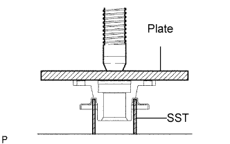 |
Using a steel plate and a press, press in a new dust deflector.
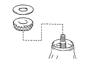
| 26. INSTALL FRONT DRIVE PINION COMPANION FLANGE SUB-ASSEMBLY |
 |
Place the companion flange on the drive pinion.
Coat the threads of a new nut with hypoid gear oil.
Using SST, install the companion flange.
 |
Using SST to hold the companion flange in place, torque the nut.
| 27. INSTALL DIFFERENTIAL SIDE BEARING RETAINER |
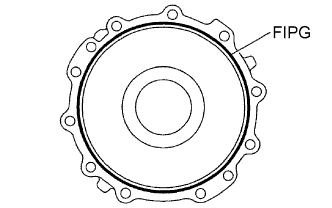 |
Remove any old FIPG material from the side bearing retainer.
Clean residual FIPG material on the contact surface using gasoline or alcohol.
Apply FIPG to the side bearing retainer, as shown.
Install the side bearing retainer with the 10 bolts.
| 28. INSPECT DRIVE PINION PRELOAD |
|
Using a torque wrench, measure the preload of the backlash between the drive pinion and ring gear.
| Item | Specified Condition |
| New bearing | 0.98 to 1.75 N*m (10 to 16 kgf*cm, 8.7 to 14 in.*lbf) |
| Reused bearing | 0.49 to 0.78 N*m (5 to 8 kgf*cm, 4.3 to 6.9 in.*lbf) |
| 29. INSPECT TOTAL PRELOAD |
|
Using a torque wrench, measure the preload with the teeth of the drive pinion and ring gear in contact.
| 30. INSPECT BACKLASH DIFFERENTIAL RING GEAR AND DIFFERENTIAL DRIVE PINION |
 |
Using SST and a dial indicator, measure the ring gear backlash.
| 31. INSPECT FRONT DRIVE PINION COMPANION FLANGE SUB-ASSEMBLY |
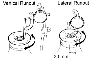 |
Using a dial indicator, measure the runout of the companion flange vertically and laterally.
| Runout | Maximum |
| Vertical runout | 0.10 mm (0.0039 in.) |
| Lateral runout | 0.10 mm (0.0039 in.) |
| 32. STAKE DRIVE PINION NUT |
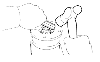 |
Using a chisel and hammer, stake the drive pinion nut.
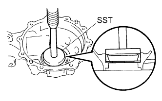
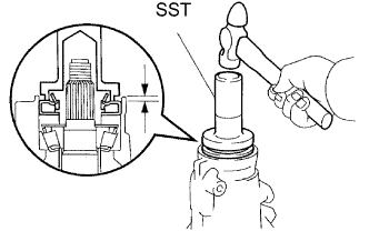
| 33. INSTALL DIFFERENTIAL SIDE GEAR SHAFT OIL SEAL |
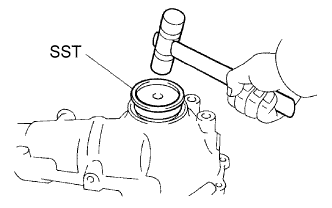 |
Coat the lip of a new oil seal with MP grease.
Using SST and a plastic-faced hammer, tap in the oil seal until its surface is flush with the differential carrier end.
| 34. INSTALL FRONT DIFFERENTIAL SIDE BEARING RETAINER DEFLECTOR |
 |
Using a brass bar and hammer, tap in the side bearing retainer deflector.
| 35. INSTALL DIFFERENTIAL SIDE GEAR INTER SHAFT SUB-ASSEMBLY |
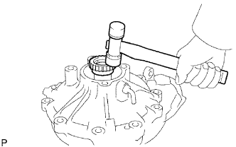 |
Install a new snap ring to the side gear inter shaft.
Using a plastic-faced hammer, tap the side gear inter shaft into the differential case.
Check that there is 2 to 3 mm (0.08 to 0.12 in.) of axial play.
Check that the side gear inter shaft cannot be completely pulled out by hand.
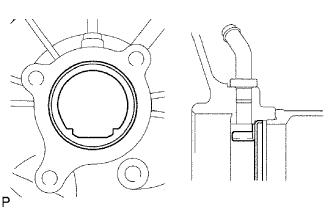
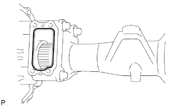
| 36. INSTALL FRONT DIFFERENTIAL TUBE ASSEMBLY |
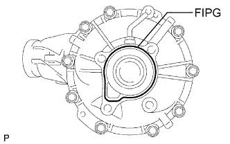 |
Remove any old FIPG material on the contact surfaces of the differential and clutch case.
Clean residual FIPG material on the contact surface using gasoline or alcohol.
Apply FIPG to the differential as shown.
Install the differential tube to the differential.
 |
Clean the threads of the 4 bolts and retainer bolt holes with toluene or trichloroethylene.
Apply adhesive to 2 or 3 threads of each bolt's end.
Install the 4 bolts.
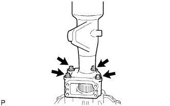
| 37. INSTALL DIFFERENTIAL VACUUM ACTUATOR ASSEMBLY |
 |
Remove any FIPG material from the contact surface of the differential and clutch case. Also, do not drop oil on the contact surfaces.
Clean residual FIPG material from the contact surfaces using gasoline or alcohol.
Apply FIPG to the differential tube as shown.
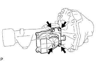 |
Clean the threads of the 4 bolts and retainer bolt holes with toluene or trichloroethylene.
Install the actuator to the differential tube.
Apply adhesive to 2 or 3 threads of each bolt's end.
Install the 4 bolts.
