PARKING BRAKE CABLE (for 2WD) > INSTALLATION |
| 1. INSTALL NO. 3 PARKING BRAKE CABLE ASSEMBLY |
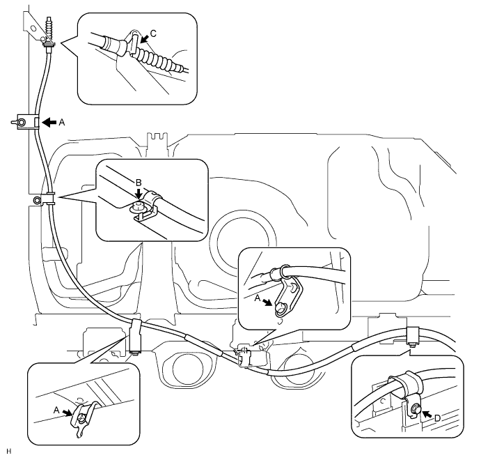
Install the cable with the 4 bolts labeled A, D and nut labeled B.
Install the No. 3 clip labeled C.
Connect the cable to the parking brake shoe lever LH and backing plate LH.
Connect the cable to the backing plate with the 2 bolts.
Connect the cable to the lever (Click here).
| 2. INSTALL NO. 2 PARKING BRAKE CABLE ASSEMBLY |
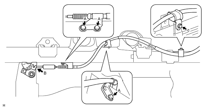
Install the cable with the 4 bolts labeled A and C.
Connect the cable to the parking brake shoe lever RH and backing plate RH.
Connect the cable to the backing plate with the 2 bolts.
Connect the cable to the lever (Click here).
Connect the cable to the equalizer labeled B.
| 3. INSTALL NO. 1 PARKING BRAKE CABLE ASSEMBLY |
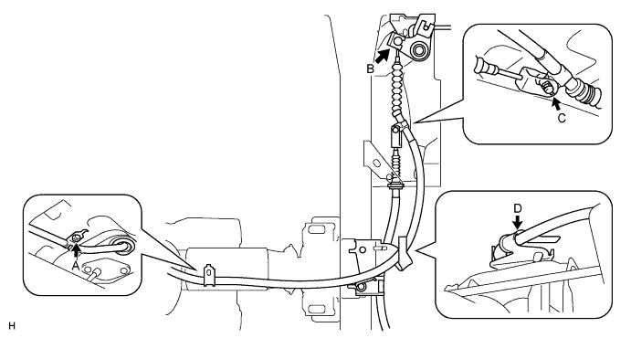
Connect the cable to the parking brake lever (Click here).
Install the cable with the bolt labeled A.
Connect the cable to the equalizer labeled B.
Connect the cable to the No. 3 cable.
Install the pin and No. 1 clip labeled C.
Attach the cable to the cable support bracket labeled D.
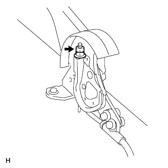
Install the No. 1 heat insulator with the 2 bolts.
| 4. CHECK REAR BRAKE DRUM INSTALLATION |
| 5. INSTALL REAR BRAKE DRUM SUB-ASSEMBLY AND NEW GASKET |
| 6. ADJUST BRAKE SHOE CLEARANCE |
| 7. INSTALL REAR WHEEL |
| 8. CHECK PARKING BRAKE LEVER TRAVEL |
Pull the lever upward with a force of approximately 200 N (20 kgf, 44 lbf) and count the number of clicks.
| 9. ADJUST PARKING BRAKE LEVER TRAVEL |
 |
Remove the lock nut.
Turn the No. 1 wire adjusting nut until the lever travel is correct.
Tighten the lock nut.
| 10. ADJUST PARKING BRAKE TURN BUCKLE |
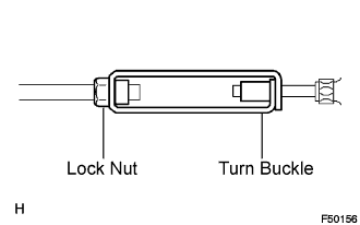 |
Loosen the lock nut and turn the buckle until the lever travel is correct.
Tighten the lock nut.
| 11. INSTALL CONSOLE BOX ASSEMBLY |
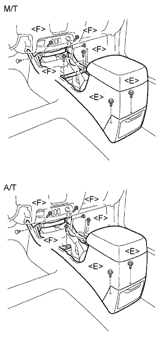 |
Install the console box with the 2 clips, 4 screws <F> and 2 bolts <E>.
| 12. INSTALL UPPER CONSOLE PANEL SUB-ASSEMBLY |
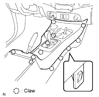 |
Attach the 12 claws to install the console panel.
| 13. INSTALL PARKING BRAKE HOLE COVER SUB-ASSEMBLY |
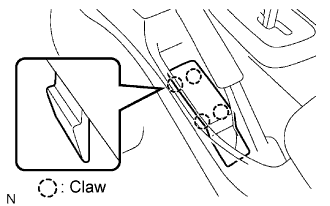 |
Attach the 4 claws to install the hole cover.
| 14. INSTALL SHIFT LEVER KNOB SUB-ASSEMBLY |
| 15. CONNECT CABLE TO NEGATIVE BATTERY TERMINAL |
| 16. PERFORM INITIALIZATION |
Perform initialization (Click here).
