PARKING BRAKE LEVER > INSTALLATION |
| 1. INSTALL PARKING BRAKE LEVER SUB-ASSEMBLY |
 |
Install the switch to the lever with the screw.
Connect the switch connector.
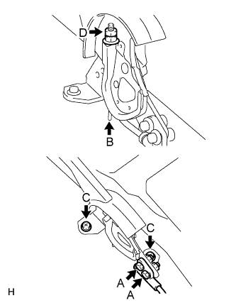
Connect the cable to the lever with the 2 bolts and 2 nuts labeled A.
Return the claw labeled B to its original position.
Install the lever with the 2 nuts labeled C.
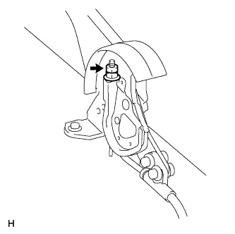
Install the wire adjusting nut and lock nut labeled D.
| 2. CHECK PARKING BRAKE LEVER TRAVEL |
Pull the lever upward with a force of approximately 200 N (20 kgf, 44 lbf) and count the number of clicks.
| 3. ADJUST PARKING BRAKE LEVER TRAVEL |
 |
Remove the lock nut.
Turn the No. 1 wire adjusting nut until the lever travel is correct.
Tighten the lock nut.
| 4. ADJUST PARKING BRAKE TURN BUCKLE |
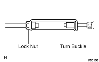 |
Loosen the lock nut and turn the buckle until the lever travel is correct.
Tighten the lock nut.
| 5. INSTALL CONSOLE BOX ASSEMBLY |
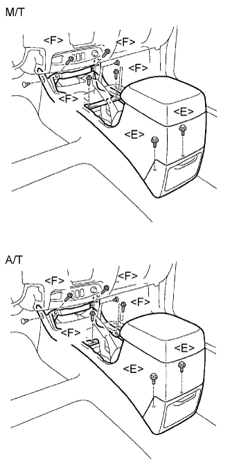 |
Install the console box with the 2 clips, 4 screws <F> and 2 bolts <E>.
| 6. INSTALL CONSOLE PANEL SUB-ASSEMBLY |
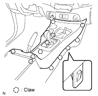 |
Attach the 12 claws to install the console panel.
| 7. INSTALL PARKING BRAKE HOLE COVER SUB-ASSEMBLY |
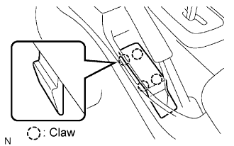 |
Attach the 4 claws to install the hole cover.
| 8. CONNECT CABLE TO NEGATIVE BATTERY TERMINAL |
| 9. PERFORM INITIALIZATION |
Perform initialization (Click here).
