TRANSFER ASSEMBLY > REASSEMBLY |
| 1. INSTALL TRANSFER DRIVE SPROCKET SUB-ASSEMBLY (A.D.D. manual shift type) |
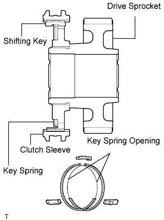 |
Apply gear oil to the connecting areas of the clutch sleeve and drive sprocket.
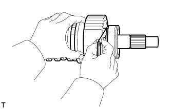
Install the clutch sleeve and 3 shifting keys to the drive sprocket with the 2 shifting key springs.
Apply gear oil to the front drive synchronizer ring's taper cone side.
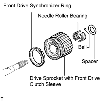 |
Install the front drive synchronizer ring.
Apply gear oil to the output shaft and needle roller bearing.
Install the needle roller bearing in the drive sprocket.
Install the drive sprocket (with clutch sleeve).
Install the ball. Install the spacer so that it is aligned with the ball.
| 2. INSTALL TRANSFER DRIVE SPROCKET SUB-ASSEMBLY (Normal shift type) |
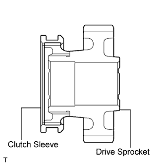 |
Apply gear oil to the connecting areas of the clutch sleeve and drive sprocket.
Install the clutch sleeve to the drive sprocket.
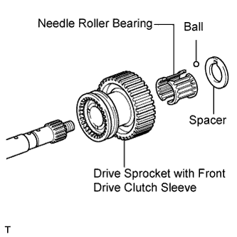 |
Apply gear oil to the output shaft and needle roller bearing.
Install the needle roller bearing in the drive sprocket.
Install the drive sprocket (with clutch sleeve).
Install the ball. Install the spacer so that it is aligned with the ball.
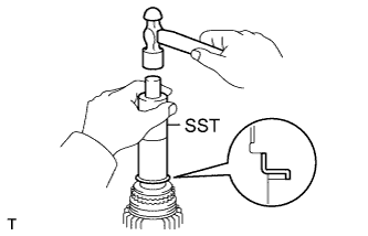
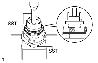
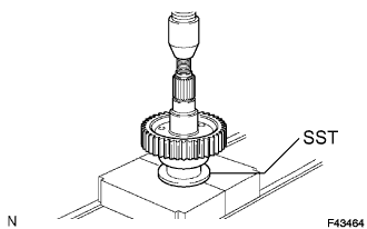
| 3. INSTALL REAR TRANSFER OUTPUT SHAFT RADIAL BALL BEARING |
Apply gear oil to the connecting areas of the output shaft and bearing.
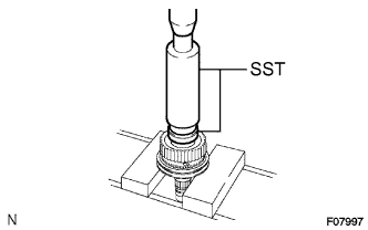 |
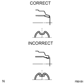
Using SST and a press, press in a new bearing with the outer race snap ring groove toward the rear.
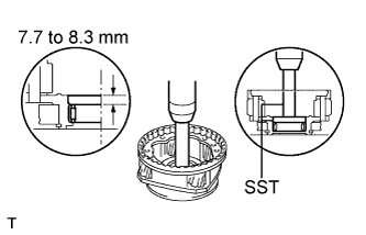
| 4. CHECK TRANSFER DRIVE SPROCKET THRUST CLEARANCE |
 |
Using a feeler gauge, measure the thrust clearance.
| 5. INSTALL TRANSFER HIGH AND LOW CLUTCH SLEEVE (M/T) |
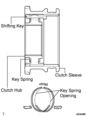 |
Apply gear oil to the connecting areas of the clutch sleeve and clutch hub.
Install the clutch sleeve and 3 shifting keys to the clutch hub with the 2 shifting key springs.
| 6. INSTALL TRANSFER HIGH AND LOW CLUTCH SLEEVE (A/T) |
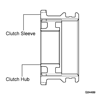 |
Apply gear oil to the connecting areas of the clutch sleeve and clutch hub.
Install the clutch to the clutch hub.
| 7. INSTALL TRANSFER CLUTCH HUB |
 |
M/T:
Apply gear oil to the connecting areas of a new key retainer and the output shaft.
M/T:
Using SST and a hammer, tap in the key retainer.
Apply gear oil to the connecting areas of the clutch hub and output shaft.
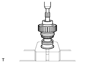 |
Using a press, press in the clutch hub.
| 8. INSTALL TRANSFER OUTPUT SHAFT SHAFT SNAP RING |
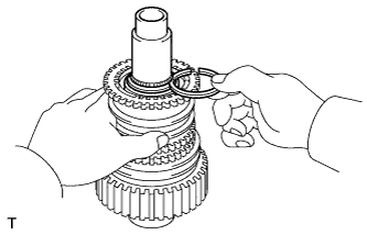 |
Select a new snap ring that allows the minimum axial free play.
| Mark | Thickness |
| K | 2.00 to 2.05 mm (0.0787 to 0.0807 in.) |
| L | 2.05 to 2.10 mm (0.0807 to 0.0827 in.) |
| A | 2.10 to 2.15 mm (0.0827 to 0.0846 in.) |
| B | 2.15 to 2.20 mm (0.0846 to 0.0866 in.) |
| C | 2.20 to 2.25 mm (0.0866 to 0.0886 in.) |
| D | 2.25 to 2.30 mm (0.0886 to 0.0906 in.) |
| E | 2.30 to 2.35 mm (0.0906 to 0.0925 in.) |
| F | 2.35 to 2.40 mm (0.0925 to 0.0945 in.) |
| G | 2.40 to 2.45 mm (0.0945 to 0.0965 in.) |
| H | 2.45 to 2.65 mm (0.0965 to 0.0984 in.) |
| J | 2.50 to 2.55 mm (0.0984 to 0.1004 in.) |
Using a snap ring expander, install the snap ring.
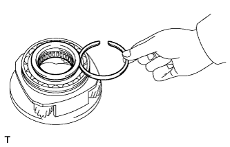
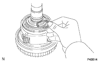
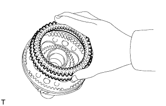
| 9. INSTALL TRANSFER LOW PLANETARY RING GEAR |
 |
Install the ring gear to the case front.
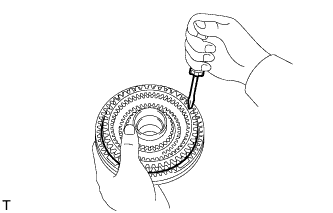
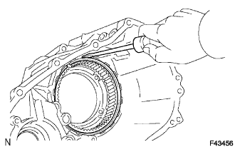 |
Using a screwdriver, install the snap ring.
| 10. INSTALL PIN |
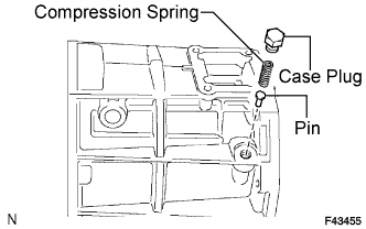 |
| 11. INSTALL COMPRESSION SPRING |
| 12. INSTALL TRANSFER CASE PLUG |
Apply sealant to the threads of the plug.
Install the plug.
| 13. INSTALL TRANSFER LOW PLANETARY GEAR BEARING |
 |
Using SST and a press, press in a new bearing.
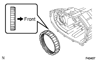
| 14. INSTALL TRANSFER INPUT SHAFT BEARING |
 |
Using SST and a press, press in a new bearing with the groove facing forward.
| 15. INSTALL TRANSFER INPUT BEARING SHAFT SNAP RING |
 |
Select a new snap ring that allows 0.1 mm (0.004 in.) or less of axial free play.
| Mark | Thickness |
| 1 | 1.45 to 1.50 mm (0.0571 to 0.0591 in.) |
| 2 | 1.50 to 1.55 mm (o.0591 to 0.0610 in.) |
| 3 | 1.55 to 1.60 mm (0.0610 to 0.0630 in.) |
| 4 | 1.60 to 1.65 mm (0.0630 to 0.0650 in.) |
| 5 | 1.65 to 1.70 mm (0.060 to 0.0669 in.) |
Using a snap ring expander, install the snap ring.
| 16. INSTALL NO. 1 TRANSFER INPUT SHAFT SEAL RING |
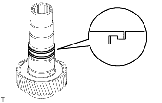 |
Apply gear oil to the 2 seal rings.
Install the 2 seal rings to the input shaft.
| 17. INSTALL TRANSFER LOW PLANETARY GEAR BEARING |
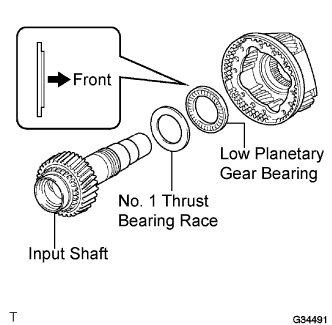 |
Install the bearing to the low planetary gear.
| 18. INSTALL NO. 1 TRANSFER THRUST BEARING RACE |
Install the bearing race to the low planetary gear.
| 19. INSTALL TRANSFER INPUT SHAFT |
Apply gear oil to the contact surfaces of the input shaft and low planetary gear.
Install the input shaft to the low planetary gear.
| 20. INSTALL MANUAL TRANSFER PLANETARY CARRIER WASHER |
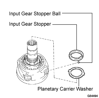 |
Apply gear oil to the washer.
Install the washer to the low planetary gear.
| 21. INSTALL TRANSFER INPUT GEAR STOPPER BALL |
Install the ball to the low planetary gear.
| 22. INSTALL TRANSFER INPUT GEAR STOPPER |
Install the stopper to the low planetary gear.
| 23. INSTALL TRANSFER INPUT GEAR STOPPER SHAFT SNAP RING |
 |
Select a new snap ring that allows 0.05 to 0.15 mm (0.0020 to 0.0059 in.) of axial free play.
| Mark | Thickness |
| A | 2.10 to 2.15 mm (0.0827 to 0.0846 in.) |
| B | 2.15 to 2.20 mm (0.0846 to 0.0866 in.) |
| C | 2.20 to 2.25 mm (0.0866 to 0.0886 in.) |
| D | 2.25 to 2.30 mm (0.0886 to 0.0906 in.) |
| E | 2.30 to 2.35 mm (0.0906 to 0.0925 in.) |
| F | 2.35 to 2.40 mm (0.0925 to 0.0945 in.) |
| G | 2.40 to 2.45 mm (0.0945 to 0.0965 in.) |
| H | 2.45 to 2.50 mm (0.0965 to 0.0984 in.) |
| J | 2.50 to 2.55 mm (0.0984 to 0.1004 in.) |
| K | 2.55 to 2.60 mm (0.1004 to 0.1204 in.) |
| L | 2.60 to 2.65 mm (0.1024 to 0.1043 in.) |
| M | 2.65 to 2.70 mm (0.1043 to 0.1063 in.) |
| N | 2.70 to 2.75 mm (0.1063 to 0.1083 in.) |
| P | 2.75 to 2.80 mm (0.1083 to 0.1102 in.) |
| Q | 2.80 to 2.85 mm (0.1102 to 0.1122 in.) |
| R | 2.85 to 2.90 mm (0.1122 to 0.1142 in.) |
| S | 2.90 to 2.95 mm (0.1142 to 0.1161 in.) |
| T | 2.95 to 3.00 mm (0.1161 to 0.1181 in.) |
| U | 3.00 to 3.05 mm (0.1181 to 0.1201 in.) |
Using a snap ring expander, install the snap ring.
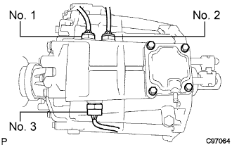
| 24. INSTALL TRANSFER CASE OIL SEAL |
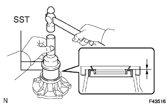
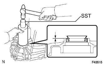 |
Using SST and a hammer, tap in a new oil seal until its surface is flush with the case upper surface (No. 1).
Coat the lip of the seal with MP grease.
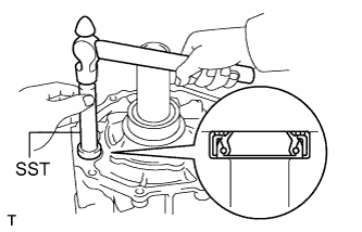 |
Using SST and a hammer, tap in a new oil seal until its surface is flush with the case upper surface (No. 2).
Coat the lip of the seal with MP grease.
| 25. INSTALL FRONT TRANSFER OUTPUT SHAFT NEEDLE ROLLER BEARING |
 |
Apply gear oil to the bearing.
Install the bearing to the low planetary gear.
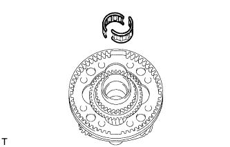
| 26. INSTALL TRANSFER LOW PLANETARY GEAR SPLINE PIECE |
 |
Install the gear spline piece to the low planetary gear.
 |
Using a screwdriver, install the snap ring.
| 27. INSTALL TRANSFER LOW PLANETARY GEAR ASSEMBLY WITH TRANSFER INPUT SHAFT |
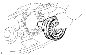 |
Install the low planetary gear with input shaft.
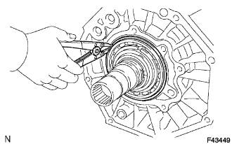 |
Using a snap ring expander, install the snap ring.
| 28. INSTALL FRONT TRANSFER DRIVE CLUTCH SYNCHRONIZER RING (M/T) |
 |
Apply gear oil to the synchronizer ring's tapered cone side.
Install the synchronizer ring to the low planetary gear.
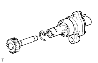
| 29. INSTALL TRANSFER OIL PUMP GEAR |
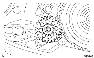 |
Apply gear oil to the sliding surface of the oil pump gear.
Install the oil pump gear with the nut.
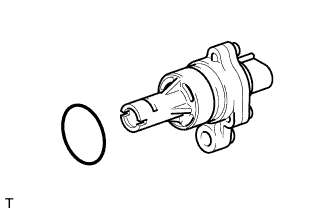
| 30. INSTALL TRANSFER OIL PUMP BODY O-RING |
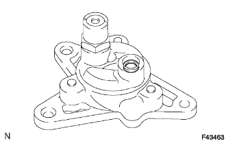 |
Coat a new O-ring with gear oil and install it to the pump body.
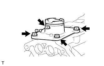
| 31. INSTALL TRANSFER OIL PUMP BODY SUB-ASSEMBLY |
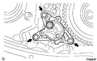 |
Install the oil pump body with the 3 bolts.
| 32. INSTALL TRANSFER CASE MAGNET |
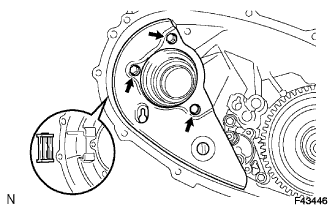 |
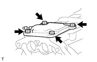
| 33. INSTALL TRANSFER OIL SEPARATOR SUB-ASSEMBLY |
Install the oil separator with the 3 bolts.
| 34. INSTALL NO. 1 TRANSFER CASE PLUG (FILLER) |
Install a new gasket and the filler plug.
| 35. INSTALL NO. 1 TRANSFER CASE PLUG (DRAIN) |
Install a new gasket and the drain plug.
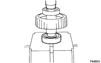
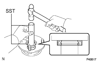
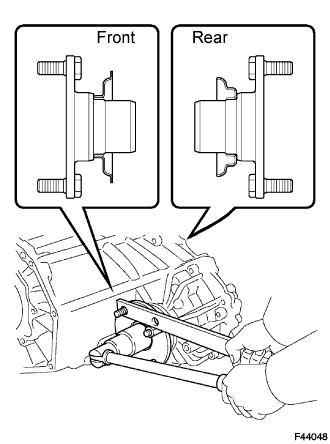
| 36. INSTALL TRANSFER INPUT GEAR RADIAL BALL BEARING |
 |
Apply gear oil to the contact surfaces of the bearing and driven sprocket.
Using SST and a press, press in a new bearing.
| 37. INSTALL TRANSFER DRIVEN SPROCKET BEARING |
 |
Apply gear oil to the contact surfaces of the bearing and driven sprocket.
Using a press, press in a new bearing.
| 38. INSTALL REAR TRANSFER OUTPUT SHAFT, TRANSFER FRONT DRIVE CHAIN AND TRANSFER DRIVEN SPROCKET |
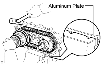 |
Mount the case rear in a vise.
Install the output shaft and driven sprocket to the front drive chain.
Install the output shaft, front drive chain and driven sprocket to the case rear.
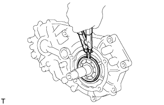 |
Using a snap ring expander, install the snap ring.
| 39. INSTALL TRANSFER HIGH AND LOW SHIFT FORK SHAFT |
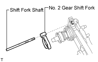 |
Apply gear oil to the connecting areas of the shift fork shaft and each part.
Install the shift fork shaft and No. 2 gear shift fork.
Install the spring and ball to the hole.
Apply sealant to the threads of the plug.
Using a hexagon wrench, install the plug.
| 40. INSTALL FRONT TRANSFER DRIVE SHIFT FORK SHAFT |
 |
Apply gear oil to the straight pin.
Install the straight pin to the hole.
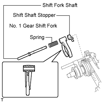 |
Apply gear oil to the connecting areas of the shift fork shaft and each part.
Install the shift fork shaft, No. 1 gear shift fork, spring and shift shaft stopper.
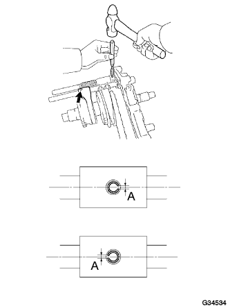 |
Using a pin punch and hammer, install the 2 slotted pins.
Install the spring and ball to the hole.
Apply sealant to the threads of the plug.
Using a hexagon wrench, install the plug.
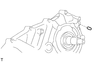
| 41. INSTALL REAR TRANSFER CASE |
 |
Apply FIPG to the case rear as shown in the illustration.
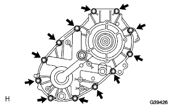 |
Install the clamp and case rear with the 12 bolts.
| 42. INSTALL TRANSFER SPEEDOMETER DRIVE GEAR |
| 43. INSTALL TRANSFER OUTPUT WASHER |
Install the 2 output washers.
| 44. INSTALL TRANSFER COVER OIL SEAL |
 |
Using SST and a hammer, tap in a new oil seal until its surface is flush with the housing upper surface.
Coat the lip of the oil seal with MP grease.
| 45. INSTALL TRANSFER EXTENSION HOUSING SUB-ASSEMBLY |
 |
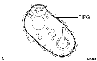
Apply FIPG to the extension housing as shown in the illustration.
Apply sealant to the threads of the bolts.
Install the extension housing with the 5 bolts.
| 46. INSTALL SPEEDOMETER DRIVEN GEAR SUB-ASSEMBLY |
 |
Install a new O-ring to the driven gear.
 |
Install the driven gear to the sensor with the clip.
| 47. INSTALL VEHICLE SPEED SENSOR |
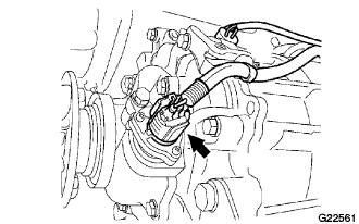 |
Install the sensor with the driven gear with the bolt.
Connect the sensor connector.
| 48. INSTALL TRANSFER OUTPUT SHAFT COMPANION FLANGE OIL SEAL (FRONT) |
 |
Using SST and a hammer, tap in a new oil seal.
| 49. INSTALL TRANSFER OUTPUT SHAFT COMPANION FLANGE OIL SEAL (REAR) |
Using SST and a hammer, tap in a new oil seal (rear) in the same way as the oil seal (front).
| 50. INSTALL OUTPUT SHAFT COMPANION FLANGE SUB-ASSEMBLY (FRONT) |
 |
Apply gear oil to the connecting areas of the companion flange and driven sprocket.
Install the companion flange to the driven sprocket.
Using SST to hold the companion flange, install a new lock nut.
 |
Using a chisel and hammer, stake the lock nut to the driven sprocket.
| 51. INSTALL OUTPUT SHAFT COMPANION FLANGE SUB-ASSEMBLY (REAR) |
Apply gear oil to the connecting areas of the companion flange and output shaft.
Using SST, install the companion flange (rear) in the same way as the companion flange (front).
| 52. INSTALL BREATHER OIL DEFLECTOR SUB-ASSEMBLY |
| 53. INSTALL TRANSFER CONTROL SHIFT LEVER RETAINER SUB-ASSEMBLY (Transfer on type) |
 |
Install the retainer with the 4 bolts.
| 54. INSTALL TRANSFER CASE COVER SUB-ASSEMBLY (Adapter on type) |
 |
Install the case cover with the 4 bolts.
| 55. INSTALL TRANSFER COVER OIL SEAL |
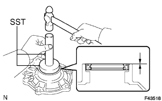 |
Using SST and a hammer, tap in a new oil seal until its surface is flush with the bearing retainer upper surface.
Coat the lip of the oil seal with MP grease.
| 56. INSTALL TRANSFER BEARING RETAINER SUB-ASSEMBLY |
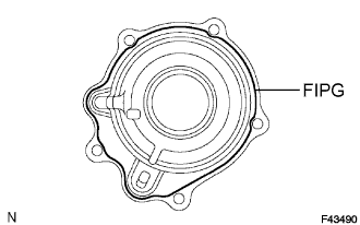 |
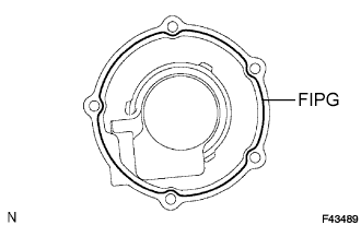
Apply FIPG to the bearing retainer as shown in the illustration.
Apply sealant to the bolt threads.
Install the retainer with the 5 bolts.
| 57. INSTALL TRANSFER GEAR SHIFT HEAD (Adapter on type) |
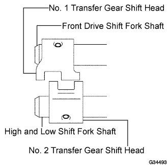 |
Install the No. 1 and No. 2 gear shift heads to the front drive shift fork shaft and high and low shift fork shaft.
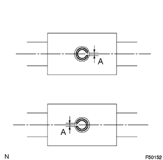 |
Using a pin punch and hammer, tap in the 2 slotted pins to the No. 1 and No. 2 gear shift heads.
| 58. INSTALL TRANSFER INDICATOR SWITCH |
 |
Install a new gasket and the indicator switch.
| No. 1 | Indicator switch (neutral position) for A/T |
| No. 2 | Indicator switch (L4 position) for A/T or M/T w/ ABS |
| No. 3 | Indicator switch (4WD) for A/T and M/T |
