TRANSFER ASSEMBLY > DISASSEMBLY |
| 1. REMOVE TRANSFER INDICATOR SWITCH |
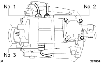 |
Remove the switches and gaskets.
| No. 1 | Indicator switch (neutral position) for A/T |
| No. 2 | Indicator switch (L4 position) for A/T or M/T w/ ABS |
| No. 3 | Indicator switch (4WD) for A/T and M/T |
| 2. REMOVE TRANSFER GEAR SHIFT HEAD (Adapter on type) |
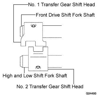 |
Using a pin punch and hammer, remove the 2 slotted pins from the No. 1 and No. 2 gear shift heads.
Remove the No. 1 and No. 2 gear shift heads from the front drive shift fork shaft, and high and low shift fork shaft.
| 3. REMOVE TRANSFER CONTROL SHIFT LEVER RETAINER SUB-ASSEMBLY (Transfer on type) |
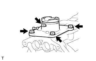 |
Remove the 4 bolts and retainer.
| 4. REMOVE TRANSFER CASE COVER SUB-ASSEMBLY (Adapter on type) |
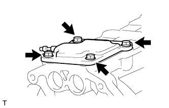 |
Remove the 4 bolts and case cover.
| 5. REMOVE BREATHER OIL DEFLECTOR |
| 6. REMOVE TRANSFER BEARING RETAINER SUB-ASSEMBLY |
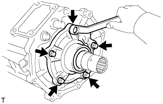 |
Remove the 5 bolts and bearing retainer.
| 7. REMOVE TRANSFER COVER OIL SEAL |
Using a screwdriver and hammer, tap out the oil seal from the bearing retainer.
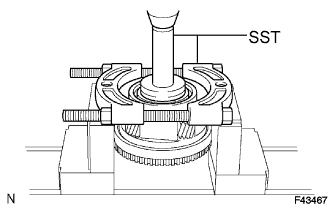
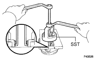
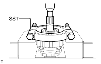
| 8. REMOVE OUTPUT SHAFT COMPANION FLANGE SUB-ASSEMBLY (FRONT) |
Using a chisel and hammer, loosen the staked part of the lock nut.
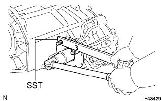 |
Using SST to hold the companion flange, remove the lock nut.
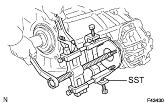 |
Using SST, remove the companion flange.
| 9. REMOVE TRANSFER OUTPUT SHAFT COMPANION FLANGE OIL SEAL (FRONT) |
Using a screwdriver and hammer, tap out the oil seal from the companion flange.
| 10. REMOVE OUTPUT SHAFT COMPANION FLANGE SUB-ASSEMBLY (REAR) |
Remove the companion flange (rear) in the same way as the companion flange (front).
| 11. REMOVE TRANSFER OUTPUT SHAFT COMPANION FLANGE OIL SEAL (REAR) |
Using a screwdriver and hammer, tap out the oil seal from the companion flange.
| 12. REMOVE VEHICLE SPEED SENSOR |
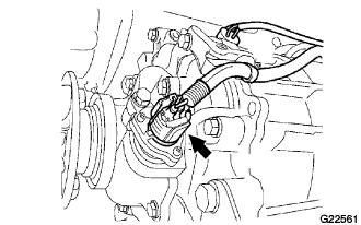 |
Disconnect the sensor connector.
Remove the bolt and sensor with the driven gear.
| 13. REMOVE SPEEDOMETER DRIVEN GEAR SUB-ASSEMBLY |
 |
Remove the clip and driven gear from the sensor.
 |
Remove the O-ring from the driven gear.
| 14. REMOVE TRANSFER EXTENSION HOUSING SUB-ASSEMBLY |
Remove the 5 bolts and extension housing.
| 15. REMOVE TRANSFER EXTENSION HOUSING TYPE T OIL SEAL |
Using a screwdriver and hammer, tap out the oil seal.
| 16. REMOVE TRANSFER OUTPUT WASHER |
| 17. REMOVE TRANSFER SPEEDOMETER DRIVE GEAR |
| 18. REMOVE REAR TRANSFER CASE |
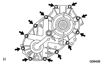 |
Remove the 12 bolts and clamp.
Remove the rear case.
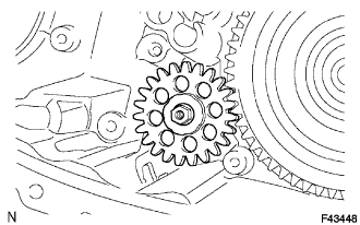
| 19. REMOVE FRONT TRANSFER DRIVE SHIFT FORK SHAFT |
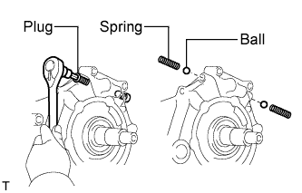 |
Using a hexagon wrench, remove the 2 plugs.
Using a magnetic finger, remove the 2 springs and 2 balls from both holes.
Mount the case rear in a vise.
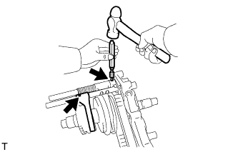 |
Using a pin punch and hammer, tap out the 2 slotted pins from the shift shaft stopper and No. 2 gear shift fork.
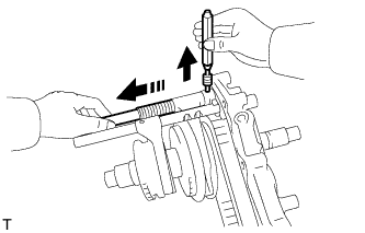 |
Hold the shift fork shaft in place by hand when removing the pin punch.
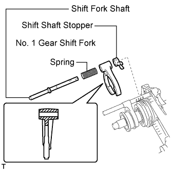 |
Remove the shift fork shaft, No. 1 gear shift fork, spring and shift shaft stopper.
 |
Using a magnetic finger, remove the straight pin.
| 20. REMOVE TRANSFER HIGH AND LOW SHIFT FORK SHAFT |
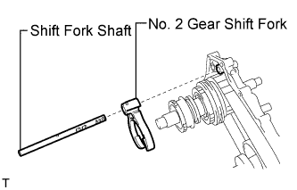 |
Remove the shift fork shaft and No. 2 gear shift fork.
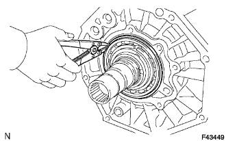
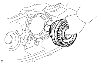
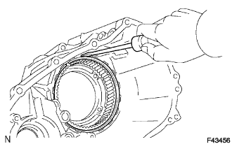
| 21. REMOVE TRANSFER REAR OUTPUT SHAFT, FRONT TRANSFER DRIVE CHAIN AND TRANSFER DRIVEN SPROCKET |
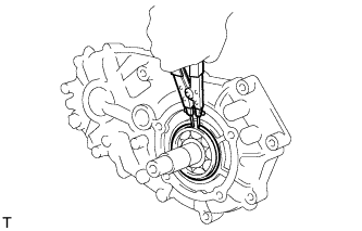 |
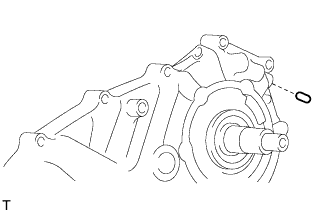
Using a snap ring expander, remove the snap ring.
 |
Using a plastic-faced hammer, carefully tap the case rear, and remove the output shaft together with the drive chain and driven sprocket.
Remove the output shaft, drive chain and driven sprocket.
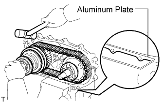
| 22. REMOVE TRANSFER DRIVEN SPROCKET BEARING |
 |
Using a press, press out the bearing.
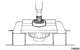
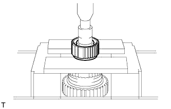
| 23. REMOVE TRANSFER INPUT GEAR RADIAL BALL BEARING |
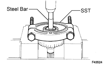 |
Using SST, a press and steel bar, press out the bearing.
| 24. REMOVE NO. 1 TRANSFER CASE PLUG (FILLER) |
Remove the filler plug and gasket.
| 25. REMOVE NO. 1 TRANSFER CASE PLUG (DRAIN) |
Remove the drain plug and gasket.
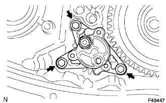
| 26. REMOVE TRANSFER OIL SEPARATOR SUB-ASSEMBLY |
 |
Remove the 3 bolts and oil separator.
| 27. REMOVE TRANSFER CASE MAGNET |
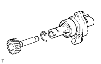
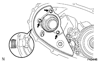
| 28. REMOVE TRANSFER OIL PUMP BODY SUB-ASSEMBLY |
 |
Remove the 3 bolts and oil pump body.
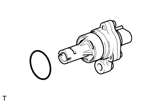
| 29. REMOVE TRANSFER OIL PUMP BODY O-RING |
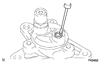 |
Using a screwdriver, remove the O-ring from the oil pump body.
| 30. REMOVE TRANSFER OIL PUMP GEAR |
 |
Remove the nut and oil pump gear.
| 31. REMOVE FRONT TRANSFER DRIVE CLUTCH SYNCHRONIZER RING (M/T) |
 |
Remove the synchronizer ring from the planetary gear.
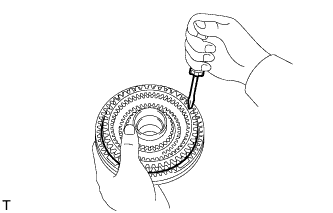
| 32. REMOVE TRANSFER LOW PLANETARY GEAR ASSEMBLY WITH TRANSFER INPUT SHAFT |
 |
Using a snap ring expander, remove the snap ring.
 |
Remove the low planetary gear with the input shaft.
| 33. REMOVE TRANSFER CASE PLUG |
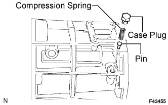 |
| 34. REMOVE COMPRESSION SPRING |
| 35. REMOVE PIN |
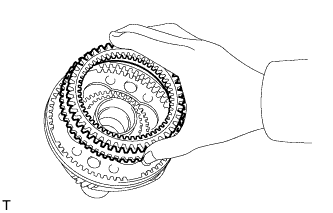
| 36. REMOVE TRANSFER LOW PLANETARY RING GEAR |
 |
Using a screwdriver, pry out the snap ring.
Remove the ring gear from the case front.
| 37. REMOVE TRANSFER CASE OIL SEAL |
Using a screwdriver and hammer, tap out the oil seal (No. 1).
Using a screwdriver and hammer, tap out the oil seal (No. 2).
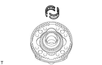
| 38. REMOVE TRANSFER LOW PLANETARY GEAR SPLINE PIECE |
 |
Using a screwdriver, pry out the snap ring.
 |
Remove the spline piece.
| 39. REMOVE TRANSFER OUTPUT SHAFT FRONT NEEDLE ROLLER BEARING |
 |
| 40. REMOVE TRANSFER INPUT GEAR STOPPER SHAFT SNAP RING |
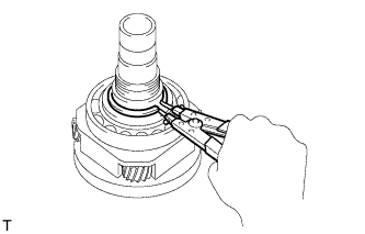 |
Using a snap ring expander, remove the snap ring.
| 41. REMOVE TRANSFER INPUT GEAR STOPPER |
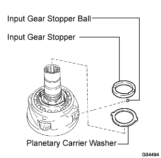 |
| 42. REMOVE TRANSFER INPUT GEAR STOPPER BALL |
| 43. REMOVE MANUAL TRANSFER PLANETARY CARRIER WASHER |
| 44. REMOVE TRANSFER INPUT SHAFT |
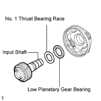 |
| 45. REMOVE NO. 1 TRANSFER THRUST BEARING RACE |
| 46. REMOVE TRANSFER LOW PLANETARY GEAR BEARING |
| 47. REMOVE NO. 1 TRANSFER INPUT SHAFT SEAL RING |
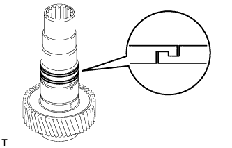 |
Remove the 2 seal rings.
| 48. REMOVE TRANSFER INPUT SHAFT BEARING |
Using a snap ring expander, remove the snap ring.
 |
Using SST and a press, press out the bearing.
| 49. REMOVE TRANSFER LOW PLANETARY GEAR BEARING |
 |
Using SST, remove the bearing.
| 50. REMOVE TRANSFER CLUTCH HUB (M/T) |
 |
Using a snap ring expander, remove the snap ring.
Remove the high and low clutch sleeve, 3 shifting keys and 2 shifting key springs.
Using a press, press out the clutch hub.
| 51. REMOVE TRANSFER CLUTCH HUB (A/T) |
Using a snap ring expander, remove the snap ring.
Remove the high and low clutch sleeve.
Using a press, press out the clutch hub.
| 52. REMOVE TRANSFER DRIVE SPROCKET SUB-ASSEMBLY (A.D.D. manual shift type) |
 |
Using SST and a press, press out the bearing.
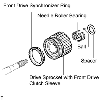 |
Remove the spacer and ball.
Remove the drive sprocket with front drive clutch sleeve.
Remove the needle roller bearing.
Remove the front drive synchronizer ring.
Remove the front drive sleeve, 3 shifting keys and 2 shifting key springs from the drive sprocket.
| 53. REMOVE TRANSFER DRIVE SPROCKET SUB-ASSEMBLY (Normal shift type) |
|
Using SST and a press, press out the bearing.
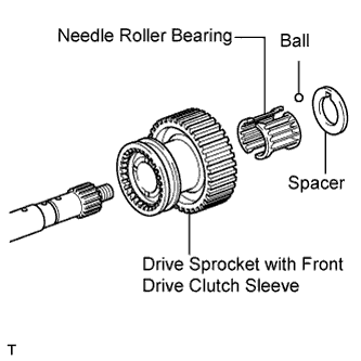 |
Remove the spacer and ball.
Remove the drive sprocket and front drive clutch sleeve.
Remove the needle roller bearing.
