TRANSFER ASSEMBLY > INSPECTION

for Preparation Click here


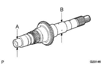
1. CHECK TRANSFER INPUT SHAFT


C111637
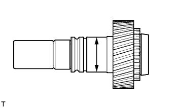
  1. Using a micrometer, measure the diameter of the input shaft journal surface.

    Minimum diameter:
    47.59 mm (1.8736 in.)

    If the diameter is less than the minimum, replace the input shaft.


    C111639
  1. Using a dial indicator, measure the inside diameter of the input shaft bushing.

    Maximum inside diameter:
    39.14 mm (1.5409 in.)

    If the inside diameter is greater than the maximum, replace the input shaft.


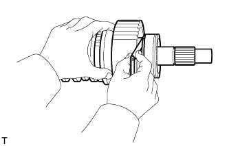
2. CHECK FRONT TRANSFER DRIVE CLUTCH SYNCHRONIZER RING (M/T)


C111640
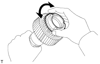
  1. While pushing in the synchronizer ring, turn the ring in both directions. Check that it cannot be rotated.


    C111641
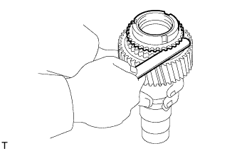
  1. Using a feeler gauge, measure the clearance between the synchronizer ring back and input shaft spline.

    Standard clearance:
    1.05 to 1.85 mm (0.0413 to 0.0728 in.)

    Minimum clearance:
    1.05 mm (0.0413 in.)

    If the clearance is less than the minimum, replace the synchronizer ring.


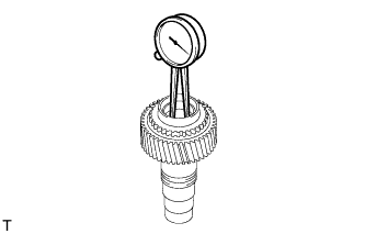
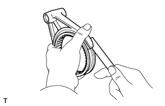
3. CHECK PLANETARY PINION GEAR THRUST CLEARANCE


C111642
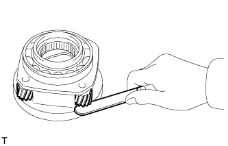
  1. Using a feeler gauge, measure the thrust clearance of the pinion gear.

    Standard clearance:
    0.11 to 0.84 mm (0.0043 to 0.0331 in.)

    Maximum clearance:
    0.84 mm (0.0331 in.)

    If the clearance is greater than the maximum, replace the low planetary gear.


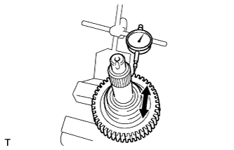
4. CHECK PLANETARY PINION GEAR RADIAL CLEARANCE


C111643
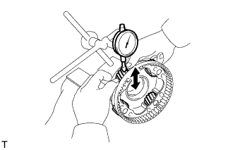
  1. Using a dial indicator, measure the radial clearance of the pinion gear.

    Standard clearance:
    0.009 to 0.038 mm (0.0004 to 0.0015 in.)

    Maximum clearance:
    0.038 mm (0.0015 in.)

    If the clearance is greater than the maximum, replace the low planetary gear.


5. CHECK TRANSFER DRIVE SPROCKET THRUST CLEARANCE


C111644
  1. Using a feeler gauge, measure the thrust clearance.

    Standard clearance:
    0.10 to 0.25 mm (0.0039 to 0.0098 in.)

    Maximum clearance:
    0.25 mm (0.0098 in.)

    If the thrust clearance is greater than the maximum, replace the drive sprocket.


6. CHECK REAR TRANSFER OUTPUT SHAFT


G023146E01
  1. Using a micrometer, measure the diameter of the output shaft journal surface.

    Minimum diameter:
    27.98 mm (1.1016 in.) for part A
    36.98 mm (1.4561 in.) for part B

    If the diameter is less than the minimum, replace the output shaft.


7. CHECK TRANSFER DRIVE SPROCKET RADIAL CLEARANCE


C111648
  1. Using a dial indicator, measure the radial clearance between the drive sprocket and output shaft with the needle roller bearing installed.

    Standard radial clearance:
    0.010 to 0.055 mm (0.0004 to 0.0022 in.)

    Maximum radial clearance:
    0.055 mm (0.0022 in.)

    If the radial clearance is greater than the maximum, replace the drive sprocket or needle roller bearing.


8. CHECK TRANSFER HIGH AND LOW CLUTCH SLEEVE AND NO. 2 TRANSFER GEAR SHIFT FORK CLEARANCE


C111649
  1. Using a feeler gauge, measure the clearance between the clutch sleeve and No. 2 gear shift fork.

    Maximum clearance:
    1.0 mm (0.039 in.)

    If the clearance is greater than the maximum, replace the clutch sleeve or No. 2 gear shift fork.


9. CHECK FRONT DRIVE CLUTCH SLEEVE AND NO. 1 TRANSFER GEAR SHIFT FORK CLEARANCE


C111649
  1. Using a feeler gauge, measure the clearance between the clutch sleeve and No. 1 gear shift fork.

    Maximum clearance:
    1.0 mm (0.039 in.)

    If the clearance is greater than the maximum, replace the clutch sleeve or No. 1 gear shift fork.