LOAD SENSING PROPORTIONING VALVE > INSTALLATION |
| 1. INSTALL LOAD SENSING PROPORTIONING VALVE ASSEMBLY |
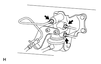 |
Install the valve with the 3 bolts.
Using SST, connect the 3 brake lines to the valve body.
| 2. CONNECT NO. 2 LOAD SENSING SPRING SHACKLE |
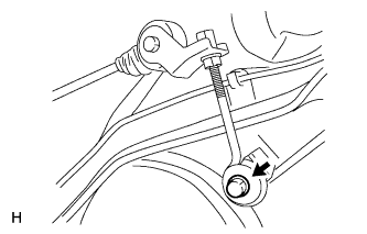 |
Connect the No. 2 shackle to the rear differential.
Install the bolt, collar and 2 cushions.
| 3. FILL RESERVOIR WITH BRAKE FLUID |
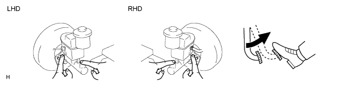
| 4. BLEED AIR FROM BRAKE MASTER CYLINDER |
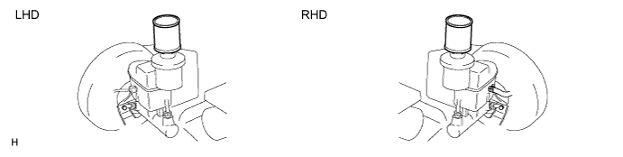
Using SST, disconnect the 2 brake lines from the master cylinder.
Slowly depress and hold the brake pedal.
Cover the outer holes with your finger, and release the pedal.
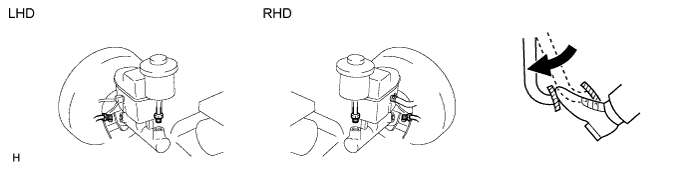
Repeat the 2 previous steps 3 or 4 times.
Using SST, connect the 2 brake lines to the master cylinder.
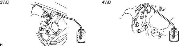
| 5. BLEED AIR FROM BRAKE LINE |
Remove the bleeder plug cap.
Connect the vinyl tube to the bleeder plugs.
Depress the pedal several times, and then loosen the bleeder plug with the pedal depressed.
When fluid stops coming out, immediately tighten the bleeder plug. Then release the pedal.
Repeat the 2 previous steps until all the air in the brake fluid is gone.
Tighten the bleeder plug.
Install the cap.
Bleed air from the brake line for each wheel by repeating the above procedures.
| 6. BLEED AIR FROM CLUTCH LINE (M/T) |
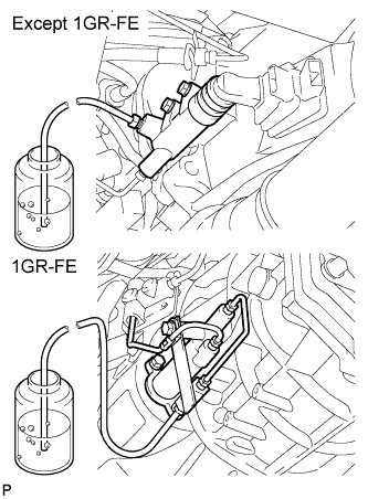 |
Remove the bleeder plug cap.
Connect the vinyl tube to the bleeder plug.
Depress the clutch pedal several times, and then loosen the bleeder plug with the pedal depressed.
At the point when fluid stops coming out, tighten the bleeder plug, and then release the clutch pedal.
Repeat the previous 2 steps until all the air in the fluid is completely bled out.
Tighten the bleeder plug.
Install the bleeder plug cap.
Check that all the air has been bled out of the clutch line.
| 7. CHECK BRAKE FLUID LEVEL IN RESERVOIR |
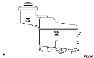 |
Check the fluid level and add fluid if necessary.
| 8. CHECK FOR BRAKE FLUID LEAKAGE |
| 9. CHECK LOAD SENSING PROPORTIONING VALVE ASSEMBLY |
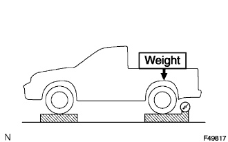 |
Set the vehicle to its curb weight.
Place weights (as necessary) on the rear deck until the rear axle load is shown below.
| Vehicle Type | Rear Axle Load |
| 2WD Single Cab | 7,845 N (800 kgf, 1,764 lbf) |
| 2WD Extra Cab | 8,336 N (850 kgf, 1,874 lbf) |
| 2WD Double Cab | 8,826 N (900 kgf, 1,984 lbf) |
| 4WD | 9,807 N (1,000 kgf, 2,205 lbf) |
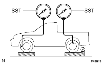 |
Set SST, and bleed air from the brake system.
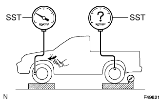 |
Raise the front brake fluid pressure to 10,000 kPa (107.6 kgf/cm2, 1,450 psi) when the brake pedal is depressed, and measure the rear brake fluid pressure.
| Vehicle Type | Rear Brake Fluid Pressure |
| 2WD | 5,260 +- 490 kPa (53.6 +- 5.0 kgf/cm2, 762 +- 71 psi) |
| 4WD | 4,450 +- 490 kPa (45.4 +- 5.0 kgf/cm2, 645 +- 71 psi) |
| 10. ADJUST LOAD SENSING PROPORTIONING VALVE ASSEMBLY |
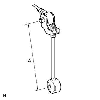 |
Adjust the length of the No. 2 shackle
For lower pressure - Lengthen "A"
For higher pressure - Shorten "A"
| Vehicle Type | "A" length |
| 2WD | 120 mm (4.764 in.) |
| 4WD | 190 mm (7.543 in.) |
| Vehicle Type | "A" length |
| 2WD | 114 to 126 mm (4.526 to 5.002 in.) |
| 4WD | 184 to 196 mm (7.305 to 7.781 in.) |
| Vehicle Type | For 1 mm (0.039 in.) of the "A" length |
| 2WD | 140 kPa (1.4 kgf/cm2, 20.5 psi) |
| 4WD | 120 kPa (1.2 kgf/cm2, 17.6 psi) |
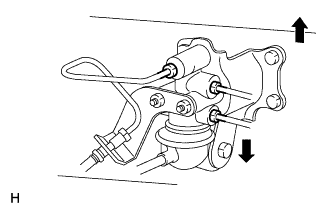 |
If the pressure cannot be adjusted by the No. 2 shackle, raise or lower the valve body.
For lower pressure - Lower the valve body
For higher pressure - Raise the valve body
Tighten the nuts.
Adjust the length of the No. 2 shackle again.
