BRAKE BOOSTER > INSTALLATION |
| 1. INSTALL BRAKE BOOSTER ASSEMBLY |
Install a new gasket to the brake booster.
 |
Install the booster with the 4 nuts.
Install the push rod clevis.
Apply lithium soap base glycol grease to the clevis pin.
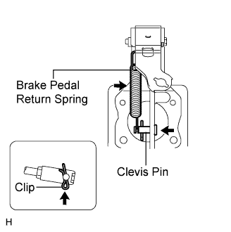 |
Install the clevis pin and clip.
Install the return spring.
| 2. CHECK AND ADJUST BRAKE BOOSTER PUSH ROD |
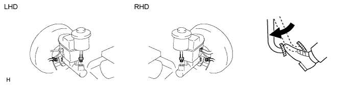
Apply chalk to the tip of an accessory tool.
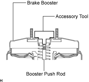 |
Place the accessory tool on the booster.
Confirm that the clearance between the booster push rod and accessory tool is equal to zero.
If there is clearance between the tool and shell of the booster, the rod is protruding too far. If chalk does not transfer from the tool to the rod, the rod is not protruding far enough. In both cases, adjust the rod in the next step.
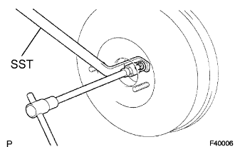 |
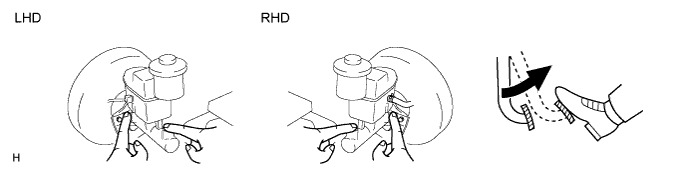
To adjust the clearance of the rod, first depress the pedal so that the rod protrudes. Then fix the rod in place using SST and rotate the hexagon cap nut to adjust the clearance.
| 3. INSTALL BRAKE MASTER CYLINDER SUB-ASSEMBLY |
Install the brake master cylinder (Click here).
| 4. FILL RESERVOIR WITH BRAKE FLUID |
| 5. BLEED AIR FROM BRAKE MASTER CYLINDER |
Using SST, disconnect the 2 brake lines from the master cylinder.
Slowly depress and hold the brake pedal.
Cover the outer holes with your finger, and release the pedal.
Repeat the 2 previous steps 3 or 4 times.
Using SST, connect the 2 brake lines to the master cylinder.
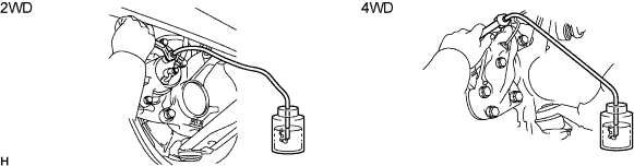
| 6. BLEED AIR FROM BRAKE LINE |
Remove the bleeder plug cap.
Connect the vinyl tube to the bleeder plugs.
Depress the pedal several times, and then loosen the bleeder plug with the pedal depressed.
When fluid stops coming out, immediately tighten the bleeder plug. Then release the pedal.
Repeat the 2 previous steps until all the air in the brake fluid is gone.
Tighten the bleeder plug.
Install the cap.
Bleed air from the brake line for each wheel by repeating the above procedures.
| 7. BLEED AIR FROM CLUTCH LINE (M/T) |
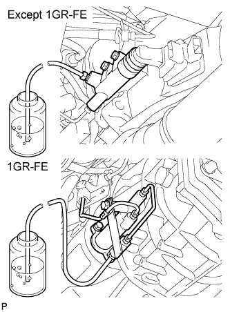 |
Remove the bleeder plug cap.
Connect the vinyl tube to the bleeder plug.
Depress the clutch pedal several times, and then loosen the bleeder plug with the pedal depressed.
At the point when fluid stops coming out, tighten the bleeder plug, and then release the clutch pedal.
Repeat the previous 2 steps until all the air in the fluid is completely bled out.
Tighten the bleeder plug.
Install the bleeder plug cap.
Check that all the air has been bled out of the clutch line.
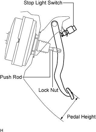
| 8. CHECK AND ADJUST BRAKE PEDAL HEIGHT |
 |
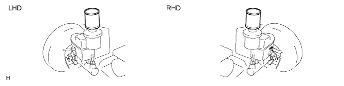
Check the pedal height.
| Model | Specified Condition |
| LHD (M/T) | 152.9 to 162.9 mm (6.020 to 6413 in.) |
| LHD (A/T) | 154.1 to 1164.1 mm (6.067 to 6.461 in.) |
| RHD (M/T) | 156.9 to 166.9 mm (6.177 to 6.571 in.) |
| RHD (A/T) | 158.1 to 168.1 mm (6.224 to 6.618 in.) |
Adjust the pedal height.
Disconnect the connector from the stop light switch.
Remove the switch.
Loosen the push rod clevis lock nut.
Adjust the pedal height by turning the push rod.
Tighten the lock nut.
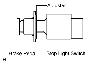 |
Insert the switch into the adjuster until it slightly touches the pedal.
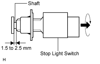 |
Turn the switch a quarter turn clockwise.
Connect the connector to the switch.
Check the switch clearance.
| 9. CHECK BRAKE PEDAL FREE PLAY |
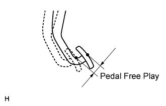 |
Stop the engine. Depress the pedal several times until there is no vacuum in the booster. Then release the pedal.
Depress the pedal until resistance is felt.
Check the pedal's free play by measuring the distance between the position in the previous step and the pedal's released position.
Check the switch clearance.
| 10. CHECK BRAKE PEDAL RESERVE DISTANCE |
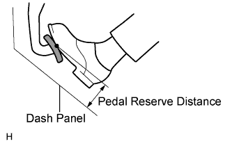 |
Release the parking brake lever. Start the engine.
Depress the pedal and check the pedal reserve distance.
Depress the pedal with a force of 490 N (50 kgf, 110 lbf).
Measure the distance between the pedal and dash panel shown in the illustration.
| Model | Specified Condition |
| LHD (2WD) | 78.0 mm (3.071 in.) |
| LHD (4WD) | 85.0 mm (3.347 in.) |
| RHD (2WD) | 82.0 mm (3.228 in.) |
| RHD (4WD) | 89.0 mm (3.504 in.) |
| 11. CHECK BRAKE FLUID LEVEL IN RESERVOIR |
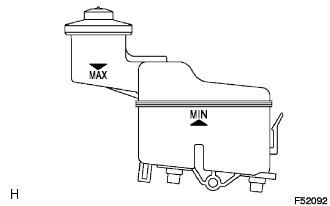 |
Check the fluid level and add fluid if necessary.
| 12. CHECK FOR BRAKE FLUID LEAKAGE |
