DTC P0443 Evaporative Emission Control System Purge Control Valve Circuit |
| DTC No. | DTC Detection Condition | Trouble Area |
| P0443 | Proper response to ECM command does not occur (1 trip detection logic) |
|
| 1.PERFORM ACTIVE TEST (VSV for EVAP) |
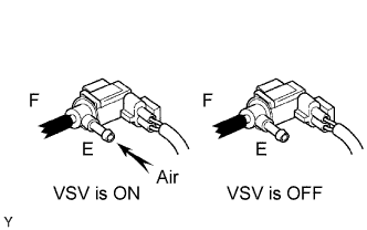 |
Disconnect the vacuum hose from the VSV for EVAP.
Connect the intelligent tester to the DLC3.
Enter the engine and turn the intelligent tester ON.
Enter the following menus: Powertrain / Engine and ECT / Active Test / Activate the VSV for EVAP Control. Press the right or left button.
Place a finger on port E. Check if the disconnected port applies suction to your finger when operating the VSV for EVAP using the intelligent tester.
| Tester Operation | Specified Condition |
| VSV is ON | Applies suction to your finger |
| VSV is OFF | Applies no suction to your finger |
|
| ||||
| NG | |
| 2.INSPECT ECM (PRG VOLTAGE) |
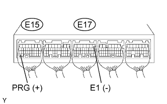 |
Turn the ignition switch ON.
Measure the voltage of the E15 and E17 ECM connectors.
| Tester Connection | Specified Condition |
| E15-34 (PRG) - E17-1 (E1) | 9 to 14 V |
|
| ||||
| NG | |
| 3.INSPECT VSV for EVAP |
|
| ||||
| OK | |
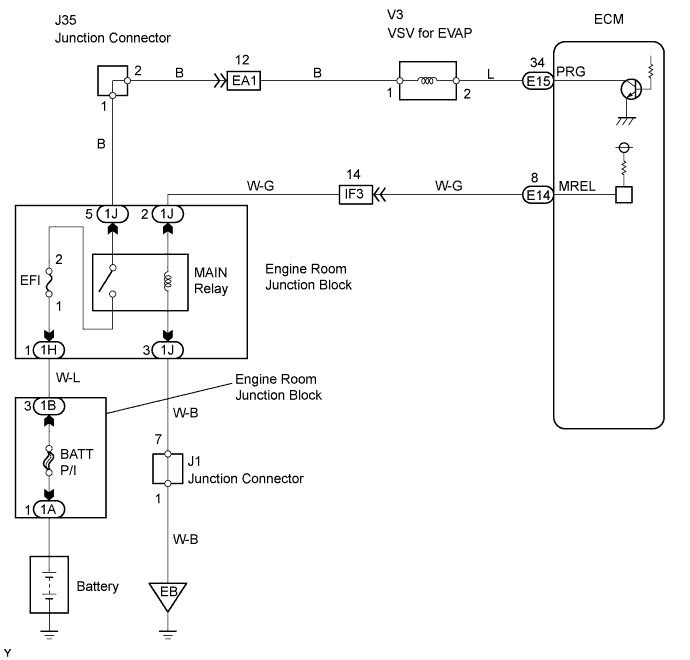
| 4.CHECK WIRE HARNESS (ECM - VSV for EVAP) |
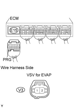 |
Disconnect the E15 connector.
Disconnect the V3 VSV connector.
Measure the resistance of the wire harness side connectors.
| Tester Connection | Specified Condition |
| V3-2 - E15-34 (PRG) | Below 1 Ω |
| V3-2 or E15-34 (PRG) - Body ground | 10 kΩ or higher |
|
| ||||
| OK | |
| 5.CHECK WIRE HARNESS (INTEGRATION RELAY - VSV for EVAP) |
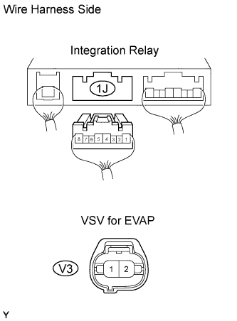 |
Disconnect the 1J integration relay connector from the engine room junction block.
Disconnect the V3 VSV connector.
Measure the resistance of the wire harness side connectors.
| Tester Connection | Specified Condition |
| V3-1 - 1J-5 | Below 1 Ω |
| V3-1 or 1J-5 - Body ground | 10 kΩ or higher |
|
| ||||
| OK | ||
| ||
