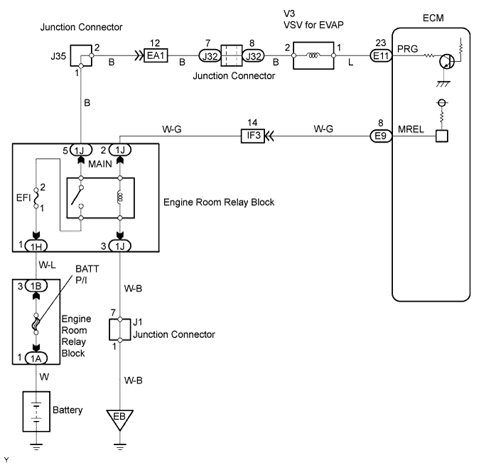
DTC P0443 Evaporative Emission Control System Purge Control Valve Circuit |
| DTC NO. | DTC Detection Condition | Trouble Area |
| P0443 | Proper response to ECM command does not occur (1 trip detection logic) |
|
| 1.PERFORM ACTIVE TEST (VSV FOR EVAP) |
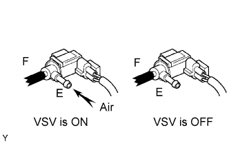 |
Disconnect the vacuum hose of the VSV.
Connect the intelligent tester to the DLC3.
Start the engine and turn the intelligent tester ON.
Select the following menu items: Powertrain / Engine and ECT / Active Test / Activate the VSV for EVAP Control. Press the right or left button.
Place your finger on port E. Check if the disconnected port applies suction to your finger when operating the VSV for EVAP using the intelligent tester.
| Tester Operation | Specified Condition |
| VSV is ON | Applies suction to your finger |
| VSV is OFF | Applies no suction to your finger |
|
| ||||
| NG | |
| 2.INSPECT ECM (PRG VOLTAGE) |
 |
Turn the ignition switch ON.
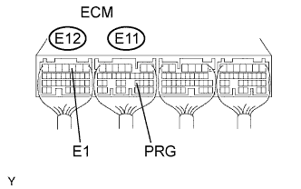
Measure the voltage of the E11 and E12 ECM connectors.
| Symbols (Terminal No.) | Specified Condition |
| E10-23 (PRG) - E11-3 (E1) | 9 to 14 V |
|
| ||||
| NG | |
| 3.INSPECT VSV FOR EVAP |
|
| ||||
| OK | |
| 4.CHECK WIRE HARNESS (VSV FOR EVAP - ECM) |
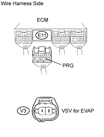 |
Disconnect the E11 ECM connector.
Disconnect the V3 VSV connector.
Measure the resistance of the wire harness side connectors.
| Symbols (Terminal No.) | Specified Condition |
| V3-1 - E11-23 (PRG) | Below 1 Ω |
| V3-1 or E11-23 (PRG) - Body ground | 10 kΩ or higher |
|
| ||||
| OK | |
| 5.CHECK WIRE HARNESS (VSV FOR EVAP - INTEGRATION RELAY) |
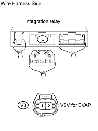 |
Disconnect the 1J integration relay connector from the engine room junction block.
Disconnect the V3 VSV connector.
Measure the resistance of the wire harness side connectors.
| Symbols (Terminal No.) | Specified Condition |
| V3-2 - 1J-5 | Below 1 Ω |
| V3-2 or 1J-5 - Body ground | 10 kΩ or higher |
|
| ||||
| OK | ||
| ||
