ANTI-LOCK BRAKE SYSTEM > ABS Warning Light Remains ON |
| 1.CHECK FOR DTC |
Turn the ignition switch ON.
Check that the ABS warning light illuminates.
Check if the same DTCs are recorded.
| Result | Proceed to |
| DTC is not output (when using intelligent tester) | A |
| DTC is not output (when not using intelligent tester) | B |
| DTC is output | C |
|
| ||||
|
| ||||
| A | |
| 2.INSPECT SKID CONTROL ECU CONNECTOR |
Check that each ECU connector is properly installed.
|
| ||||
| OK | |
| 3.READ VALUE OF INTELLIGENT TESTER (ECU IG POWER VOLTAGE) |
Using the Data List, check for proper functioning of the ECU IG power voltage.
| Item | Measurement Item / Range (Display) | Normal Condition | Diagnostic Note |
| ECU IG Power Voltage | ECU power supply voltage / TOO LOW / NORMAL / TOO HIGH | TOO HIGH: more than 14.0 V NORMAL: 10 to 14 V TOO LOW: Below 10 V | - |
| Result | Proceed to |
| Display is NORMAL | A |
| Display is not NORMAL | B |
|
| ||||
| A | |
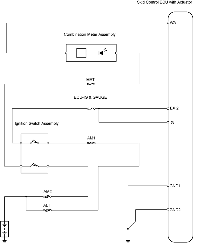
| 4.CHECK WIRE HARNESS (SKID CONTROL ECU - BATTERY) |
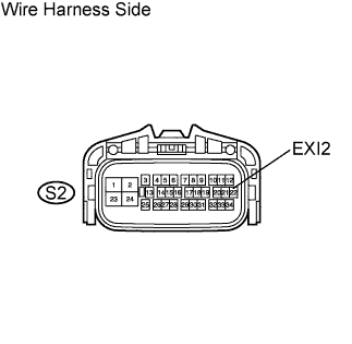 |
Disconnect the S2 ECU connector.
Measure the voltage of the wire harness side connector.
| Tester Connection | Condition | Specified Condition |
| S2-22 (EXI2) - Body ground | Ignition switch ON | 10 to 14 V |
|
| ||||
| OK | |
| 5.CHECK ABS WARNING LIGHT |
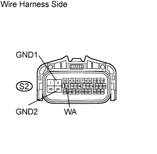 |
Disconnect the S2 ECU connector.
Turn the ignition switch ON.
Using a service wire, connect terminal WA to GND1 or GND2 of the S2 ECU connector. Check the ABS warning light.
Turn the ignition switch OFF.
Remove the service wire.
Turn the ignition switch ON. Check the ABS warning light.
|
| ||||
| OK | |
| 6.CHECK WIRE HARNESS (SKID CONTROL ECU - COMBINATION METER ASSEMBLY AND BODY GROUND) |
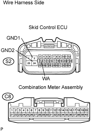 |
Disconnect the S2 ECU
Disconnect the C8 meter connector.
Measure the resistance of the wire harness side connectors.
| Tester Connection | Specified Condition |
| S2-13 (WA) - C8-38 | Below 1 Ω |
| S2-13 (WA) - Body ground | 10 kΩ or higher |
| S2-2 (GND1) - Body ground | Below 1 Ω |
| S2-24 (GND2) - Body ground | Below 1 Ω |
|
| ||||
| OK | ||
| ||
| 7.INSPECT SKID CONTROL ECU CONNECTOR |
Check that each ECU connector is properly installed.
|
| ||||
| OK | |
| 8.CHECK WIRE HARNESS (SKID CONTROL ECU - BATTERY) |
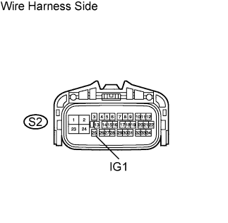 |
Disconnect the S2 ECU connector.
Measure the voltage of the wire harness side connector.
| Tester Connection | Condition | Specified Condition |
| S2-25 (IG1) - Body ground | Ignition switch ON | 10 to 14 V |
|
| ||||
| OK | |
| 9.CHECK ABS WARNING LIGHT |
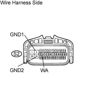 |
Disconnect the S2 ECU connector.
Turn the ignition switch ON.
Using a service wire, connect terminal WA to GND1 or GND2 of the S2 ECU connector. Check the ABS warning light.
Turn the ignition switch OFF.
Remove the service wire.
Turn the ignition switch ON. Check the ABS warning light.
|
| ||||
| OK | |
| 10.CHECK WIRE HARNESS (SKID CONTROL ECU - COMBINATION METER ASSEMBLY AND BODY GROUND) |
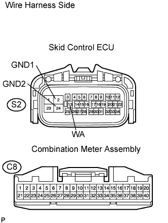 |
Disconnect the S2 ECU connector.
Disconnect the C8 meter connector.
Measure the resistance of the wire harness side connectors.
| Tester Connection | Specified Condition |
| S2-13 (WA) - C8-38 | Below 1 Ω |
| S2-13 (WA) - Body ground | 10 kΩ or higher |
| S2-2 (GND1) - Body ground | Below 1 Ω |
| S2-24 (GND2) - Body ground | Below 1 Ω |
|
| ||||
| OK | ||
| ||
| 11.CHECK WIRE HARNESS |
|
Disconnect the S2 ECU connector.
Measure the voltage of the wire harness side connector.
| Tester Connection | Condition | Specified Condition |
| S2-25 (IG1) - Body ground | Ignition switch ON | 10 to 14 V |
|
| ||||
| OK | ||
| ||
