DTC C1243/43 Acceleration Sensor Stuck Malfunction |
DTC C1244/44 Open or Short in Deceleration Sensor Circuit |
DTC C1245/45 Acceleration Sensor Output Malfunction |
| DTC No. | DTC Detection Condition | Trouble Area |
| C1243/43 | Following condition repeats 16 times: GL1 does not change when vehicle decelerates from 30 km/h (19 mph) to 0 km/h (0 mph) |
|
| C1244/44 | When one of following (1 to 3) is detected: 1. Deceleration G calculated by ECU based on GL1 signal is not within -1.5 and 1.5 G for 1.2 sec. 2. When sensor operating voltage is not within 4.75 to 5.25 V 3. Deceleration sensor malfunction signal occurs more than 7 times |
|
| C1245/45 | Difference between value calculated from deceleration sensor value and vehicle speed exceeds 0.35 G for at least 60 seconds |
|
| 1.CHOOSE DIAGNOSIS METHOD |
Choose the diagnosis method.
| Method | Proceed to |
| Using intelligent tester | A |
| Not using intelligent tester | B |
|
| ||||
| A | |
| 2.READ VALUE OF INTELLIGENT TESTER (DECELERATION SENSOR 1) |
Check the Data List for proper functioning of the deceleration sensor.
| Item | Measurement Item / Range (Display) | Normal Condition | Diagnostic Note |
| Deceleration Sensor 1 | Deceleration sensor 1 reading / min.: -1.869 G, max.: 1.869 G | Approx. 0 +- 0.13 G when vehicle is not moving. | Reading changes when vehicle is shaken |
|
| ||||
| NG | |
| 3.INSPECT DECELERATION SENSOR |
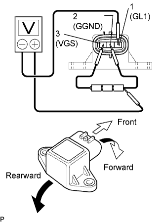 |
Remove the console box and deceleration sensor.
Connect 3 dry cell batteries of 1.5 V in series.
Check the output voltage of terminal 1 (GL1) when the sensor is tilted forward and rearward.
| Tester Connection | Sensor Position | Specified Condition |
| 1 (GL1) - Battery's negative (-) lead | Horizontal | Approx 2.5 V |
| 1 (GL1) - Battery's negative (-) lead | Tilted forward | Approx 0.5 to 2.5 V |
| 1 (GL1) - Battery's negative (-) lead | Tilted rearward | Approx 2.5 to 4.5 V |
|
| ||||
| OK | |
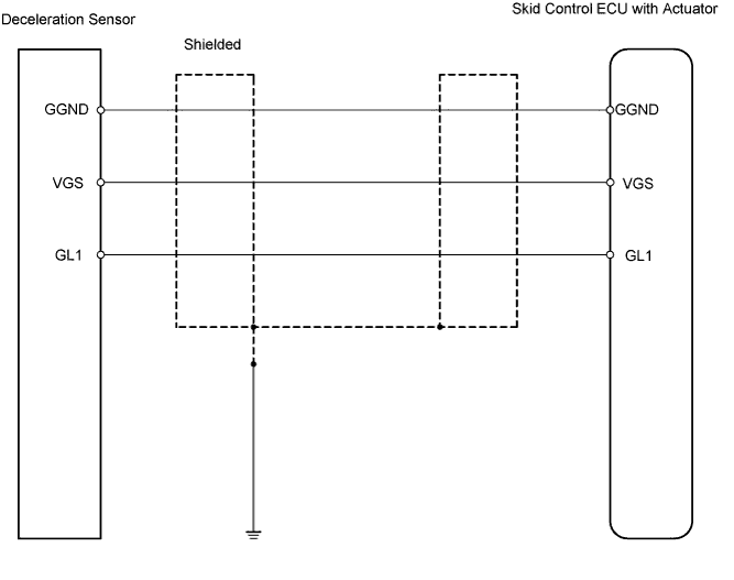
| 4.CHECK WIRE HARNESS (SKID CONTROL ECU - DECELERATION SENSOR) |
 |
Disconnect the S2 ECU connector.
Disconnect the A17 sensor connector.
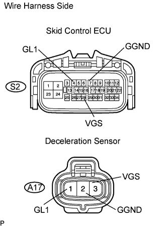
Measure the resistance of the wire harness side connectors.
| Tester Connection | Specified Condition |
| S2-4 (GL1) - A17-1 (GL1) | Below 1 Ω |
| S2-7 (GGND) - A17-2 (GGND) | Below 1 Ω |
| S2-28 (VGS) - A17-3 (VGS) | Below 1 Ω |
| A17-1 (GL1) - Body ground | 10 kΩ or higher |
| A17-2 (GGND) - Body ground | 10 kΩ or higher |
| A17-3 (VGS) - Body ground | 10 kΩ or higher |
|
| ||||
| OK | |
| 5.CHECK FOR DTC |
Install the deceleration sensor to the vehicle.
Clear the DTCs.
Drive the vehicle at 6 km/h (4 mph) or more.
Check for DTCs.
| Result | Proceed to |
| DTC is output | A |
| DTC is not output | B |
|
| ||||
| A | ||
| ||
