DTC C0200/31 Right Front Wheel Speed Sensor Signal Malfunction |
DTC C0205/32 Left Front Wheel Speed Sensor Signal Malfunction |
DTC C1235/35 Foreign Object is Attached on Tip of Front Speed Sensor RH |
DTC C1236/36 Foreign Object is Attached on Tip of Front Speed Sensor LH |
| DTC No. | DTC Detection Condition | Trouble Area |
| C0200/31 C0205/32 | When one of following occurs
|
|
| C1235/35 C1236/36 | At vehicle speed of 20 km/h (12 mph) or more, condition that noise is included in speed sensor signal continues for 5 sec. or more. |
|
| 1.CHOOSE DIAGNOSIS METHOD |
Choose the diagnosis method.
| Method | Proceed to |
| Using intelligent tester | A |
| Not using intelligent tester | B |
|
| ||||
| A | |
| 2.READ VALUE OF INTELLIGENT TESTER (FRONT SPEED SENSOR) |
Check Data List for proper functioning of the front speed sensor.
| Item | Measurement Item / Range (Display) | Normal Condition | Diagnostic Note |
| FR Wheel Speed | Wheel speed sensor (FR) reading / min.: 0 km/h (0 mph), max.: 326 km/h (202 mph) | Actual wheel speed | Speed similar to that of speedometer |
| FL Wheel Speed | Wheel speed sensor (FL) reading / min.: 0 km/h (0 mph), max.: 326 km/h (202 mph) | Actual wheel speed | Speed similar to that of speedometer |
|
| ||||
| OK | |
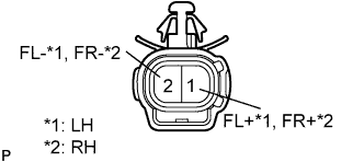
| 3.INSPECT SPEED SENSOR AND SENSOR ROTOR SERRATIONS |
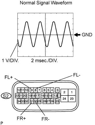 |
Connect an oscilloscope to terminals 31 (FR+) and 30 (FR-), and 9 (FL+) and 8 (FL-) of the S2 skid control ECU connector.
Drive the vehicle at about 30 km/h (19 mph), and check the signal waveform.
|
| ||||
| OK | ||
| ||
| 4.INSPECT FRONT SPEED SENSOR |
 |
Disconnect the S4 and S5 sensor connectors.
Measure the resistance of the speed sensors.
| Tester Connection | Specified Condition |
| 1 (FL+) - 2 (FL-) | 0.6 to 1.8 kΩ |
| 1 (FL+) - Body ground | 10 kΩ or higher |
| 2 (FL-) - Body ground | 10 kΩ or higher |
| Tester Connection | Specified Condition |
| 1 (FR+) - 2 (FR-) | 0.6 to 1.8 kΩ |
| 1 (FR+) - Body ground | 10 kΩ or higher |
| 2 (FR-) - Body ground | 10 kΩ or higher |
|
| ||||
| OK | |
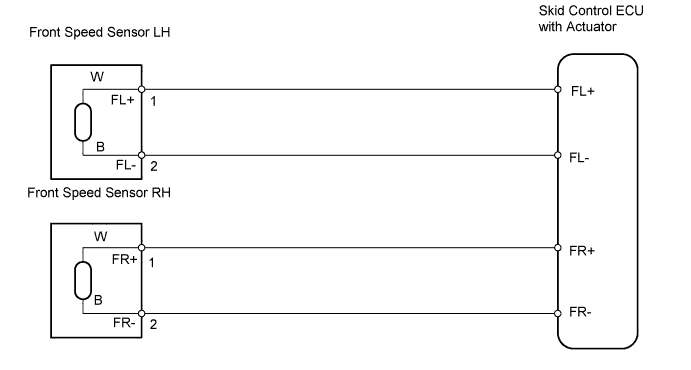
| 5.CHECK WIRE HARNESS (SKID CONTROL ECU - FRONT SPEED SENSOR) |
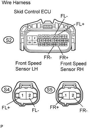 |
Disconnect the S2 ECU connector.
Disconnect the S4 and S5 speed sensor connectors.
Measure the resistance of the wire harness side connectors.
| Tester Connection | Specified Condition |
| S2-9 (FL+) - S4-1 (FL+) | Below 1 Ω |
| S2-8 (FL-) - S4-2 (FL-) | Below 1 Ω |
| S4-1 (FL+) - Body ground | 10 kΩ or higher |
| S4-2 (FL-) - Body ground | 10 kΩ or higher |
| Tester Connection | Specified Condition |
| S2-31 (FR+) - S5-1 (FR+) | Below 1 Ω |
| S2-30 (FR-) - S5-2 (FR-) | Below 1 Ω |
| S5-1 (FR+) - Body ground | 10 kΩ or higher |
| S5-2 (FR-) - Body ground | 10 kΩ or higher |
|
| ||||
| OK | |
| 6.INSPECT SPEED SENSOR AND SENSOR ROTOR SERRATIONS |
|
Connect an oscilloscope to terminals 31 (FR+) and 30 (FR-), and 9 (FL+) and 8 (FL-) of the S2 skid control ECU connector.
Drive the vehicle at about 30 km/h (19 mph), and check the signal waveform.
|
| ||||
| OK | |
| 7.CHECK IF DTC OUTPUT RECURS |
Clear the DTCs.
Drive the vehicle at approximately 30 km/h (19 mph) or more for 60 seconds or more.
Check for DTCs.
| Result | Proceed to |
| DTC is output | A |
| DTC is not output | B |
|
| ||||
| A | ||
| ||
| 8.INSPECT FRONT SPEED SENSOR INSTALLATION |
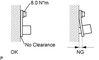 |
Check the speed sensor installation.
|
| ||||
| OK | |
| 9.INSPECT SPEED SENSOR TIP |
Remove the front speed sensor.
Check the sensor tip.
|
| ||||
| OK | |
| 10.INSPECT SPEED SENSOR ROTOR |
Remove the front axle hub.
Check the sensor rotor serrations.
|
| ||||
| OK | |
| 11.CHECK IF DTC OUTPUT RECURS |
Clear the DTCs.
Drive the vehicle at approximately 30 km/h (19 mph) or more for 60 seconds or more.
Check for DTCs.
| Result | Proceed to |
| DTC is output | A |
| DTC is not output | B |
|
| ||||
| A | ||
| ||
