REAR AXLE SHAFT > INSTALLATION |
| 1. INSTALL REAR AXLE SHAFT BEARING |
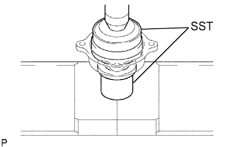 |
Using SST and a press, press in a new bearing.
| 2. INSTALL REAR AXLE SHAFT OUTER OIL SEAL |
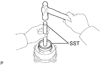 |
Using SST and a hammer, tap in a new oil seal.
| 3. INSTALL REAR AXLE HUB BOLT |
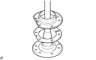 |
Install a new deflector gasket and the deflector to the axle shaft.
 |
Pass the bolts through the axle hub.
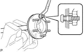
Temporarily install a plate washer and nut to the bolt. Install the hub bolt by tightening the nut.
Remove the nut and plate washer.
| 4. INSTALL BACKING PLATE |
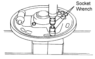 |
Position the backing plate on the bearing case.
Using 2 socket wrenches, press in the serration bolts.
| 5. INSTALL REAR AXLE SHAFT IN BACKING PLATE |
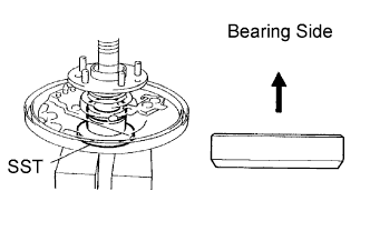 |
Coat a new oil seal lip with MP grease.
Install the backing plate and bearing retainer on the rear axle shaft.
Using SST and a press, press in the axle shaft into the backing plate.
Using snap ring expander, install a new snap ring.
| 6. INSTALL REAR AXLE BEARING RETAINER AND ABS SPEED SENSOR ROTOR (w/ ABS) |
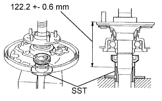 |
Using SST and a press, press in a new sensor rotor and new bearing retainer to the axle shaft until length is within the standard range.
| 7. REMOVE REAR AXLE SHAFT OIL SEAL |
 |
Using SST and a hammer, tap in a new oil seal.
Coat the lip of the oil seal with MP grease.
| 8. INSTALL REAR AXLE SHAFT WITH BACKING PLATE |
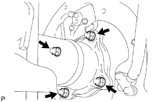 |
Install a new O-ring.
Install the axle shaft with the 4 nuts.
| 9. INSTALL BRAKE LINE AND PARKING BRAKE CABLE |
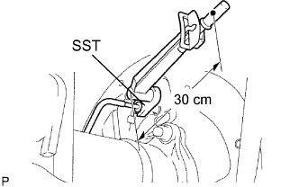 |
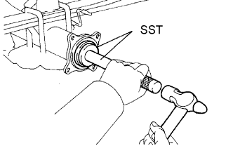
Using SST, connect the brake tube.
Connect the parking brake cable with the 2 bolts.
| 10. INSTALL REAR BRAKE SHOE (for 2WD) |
Install the rear brake shoe (Click here).
| 11. INSTALL REAR BRAKE SHOE (for 4WD) |
Install the rear brake shoe (Click here).
| 12. INSTALL BRAKE DRUM |
| 13. INSTALL SPEED SENSOR REAR LH (w/ ABS) |
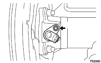 |
Install the sensor with the bolt.
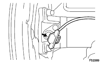 |
Connect the sensor connector.
| 14. BLEED AIR FROM BRAKE LINE |
Bleed air from the brake line (Click here).
| 15. CHECK BRAKE FLUID LEVEL IN RESERVOIR |
Check the brake fluid level in the reservoir (Click here).
| 16. CHECK FOR BRAKE FLUID LEAKAGE |
| 17. INSTALL REAR WHEEL |
| 18. INSPECT AND ADJUST PARKING BRAKE LEVER TRAVEL |
Inspect and adjust parking brake lever travel (Click here).
| 19. CHECK ABS SPEED SENSOR SIGNAL (w/ ABS) |
Check ABS speed sensor signal (Click here).
