FRONT AXLE HUB (for 2WD) > INSTALLATION |
| 1. INSTALL FRONT AXLE HUB INNER BEARING |
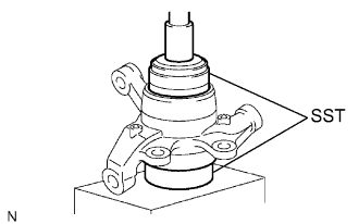 |
Using SST and a press, press a new bearing into the steering knuckle.
Using snap ring pliers, install a new snap ring.
| 2. INSTALL FRONT AXLE HUB OIL SEAL |
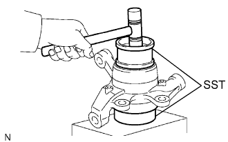 |
Using SST and a plastic-faced hammer, tap in a new oil seal.
Apply MP grease to the lip of the oil seal.
| 3. INSTALL AXLE HUB TO STEERING KNUCKLE |
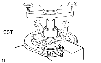 |
Install the dust cover to the steering knuckle with the 3 bolts.
Using SST and a press, press the axle hub into the steering knuckle.
| 4. INSTALL FRONT AXLE HUB NUT AND ABS SPEED SENSOR ROTOR OR SPACER |
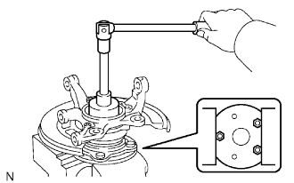 |
w/ ABS:
Install the ABS speed sensor rotor.
w/o ABS:
Install the spacer.
Install a new nut to the axle hub.
Using a chisel and hammer, stake the nut.
| 5. INSTALL KNUCKLE GREASE RETAINER CAP |
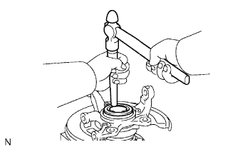 |
Using a brass bar and hammer, install the knuckle grease retainer cap.
| 6. INSTALL FRONT AXLE HUB ASSEMBLY |
| 7. INSTALL FRONT SUSPENSION UPPER ARM ASSEMBLY LH |
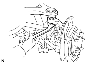 |
Install the upper arm with the nut.
Install the clip.
| 8. INSTALL FRONT SUSPENSION LOWER ARM ASSEMBLY WITH ATTACHMENT LH |
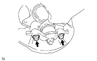 |
Install the suspension arm with the 2 bolts.
| 9. INSTALL TIE ROD END SUB-ASSEMBLY |
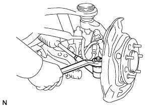 |
Install the tie rod end with the nut.
Install a new cotter pin.
| 10. INSTALL FRONT DISC |
| 11. INSTALL FRONT INSTALL SPEED SENSOR |
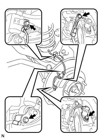 |
Install the speed sensor with the bolt.
Connect the 3 clamps with the 3 bolts.
| 12. INSTALL FRONT DISC BRAKE CALIPER ASSEMBLY |
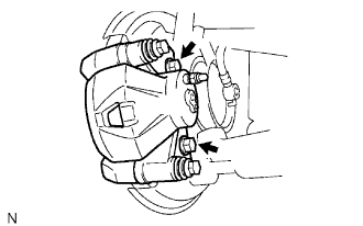 |
Install the brake caliper with the 2 bolts.
Connect the brake hose to the brake caliper with the union bolt and gasket.
| 13. BLEED AIR FROM BRAKE LINE |
Bleed air from the brake line (Click here).
| 14. CHECK BRAKE FLUID LEVEL IN RESERVOIR |
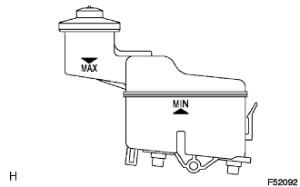 |
Check the fluid level and add fluid if necessary.
| 15. CHECK FOR BRAKE FLUID LEAKAGE |
Check for brake fluid leakage (Click here).
| 16. INSTALL FRONT WHEEL |
| 17. CHECK ABS SPEED SENSOR SIGNAL |
Check ABS speed sensor signal (Click here).
