REAR PROPELLER SHAFT ASSEMBLY > REASSEMBLY |
| 1. INSTALL UNIVERSAL JOINT SPIDER ASSEMBLY |
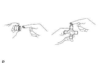 |
Apply MP grease to a new spider and bearings.
Fit the spider into the flange yoke.
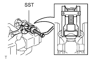 |
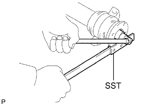
Using SST, install the 2 spider bearings to the spider.
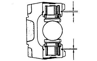 |
Using SST, adjust the spider bearings so that: 1) the flange yoke does not overlap the snap ring grooves of the spider bearings, and the grooves are as wide as possible; and 2) the groove width on both sides is the same.
Install 2 new snap rings to the installed spider bearings. The snap rings must have equal thickness which will allow 0 to 0.05 mm (0 to 0.002 in.) axial play.
| Parts No. | Thickness | Mark |
| 90520-T0007 | 2.19 mm (0.0862 in.) | F |
| 90520-T0008 | 2.21 mm (0.0870 in.) | G |
| 90520-T0009 | 2.23 mm (0.0877 in.) | H |
| 90520-T0010 | 2.25 mm (0.0885 in.) | J |
| 90520-T0011 | 2.27 mm (0.0893 in.) | K |
| 90520-T0012 | 2.29 mm (0.0901 in.) | 1 |
| 90520-T0013 | 2.31 mm (0.0909 in.) | 2 |
| 90520-T0014 | 2.33 mm (0.0917 in.) | 3 |
| 90520-T0015 | 2.35 mm (0.0925 in.) | 4 |
| 90520-T0016 | 2.37 mm (0.0933 in.) | 5 |
| 90520-T0017 | 2.39 mm (0.0940 in.) | 6 |
| 90520-T0018 | 2.41 mm (0.0948 in.) | 7 |
| 90520-T0019 | 2.43 mm (0.0956 in.) | 8 |
| 90520-T0020 | 2.45 mm (0.0964 in.) | N |
| 90520-T0021 | 2.47 mm (0.0972 in.) | 10 |
| 90520-T0022 | 2.49 mm (0.0980 in.) | A |
| 90520-T0023 | 2.51 mm (0.0988 in.) | B |
| 90520-T0024 | 2.53 mm (0.0996 in.) | C |
| 90520-T0025 | 2.55 mm (0.1003 in.) | D |
| 90520-T0026 | 2.57 mm (0.1011 in.) | E |
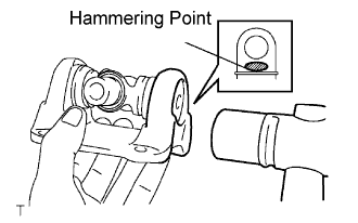 |
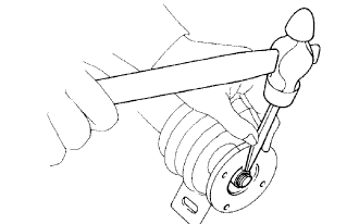
Using a hammer, tap the flange yoke until there is no clearance between the spider bearings and snap rings.
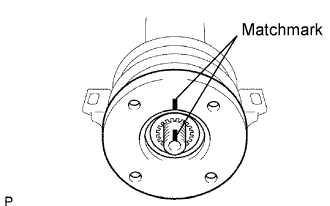
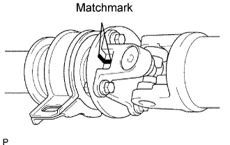
Align the matchmarks on the flange yoke and sleeve yoke.
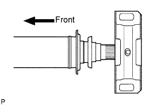
Install new spider bearings on the sleeve yoke side.
| 2. INSPECT UNIVERSAL JOINT SPIDER ASSEMBLY |
Check the spider bearings for wear or damage.
Check each spider bearing's axial play by turning the yoke while holding the shaft tightly.
| 3. INSTALL NO. 1 CENTER SUPPORT BEARING ASSEMBLY |
 |
Install the center support bearing to the intermediate shaft.
 |
Coat the splines of the intermediate shaft with MP grease.
Align the matchmarks on the flange coupling and intermediate shaft.
Install the washer.
 |
Using SST to hold the flange, press the bearing into position by tightening a new nut.
Loosen the nut.
Torque the nut again.
 |
Using a chisel and hammer, stake the lock nut.
 |
Align the matchmarks on the flanges and connect the flanges with the 4 washers and 4 nuts.
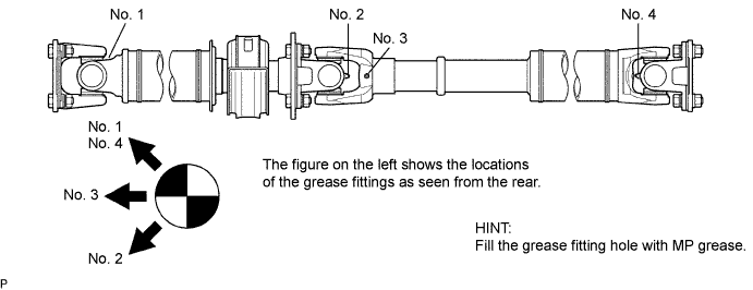
| 4. INSPECT PROPELLER WITH CENTER BEARING SHAFT ASSEMBLY (for 4WD) |
When replacing the spider bearing, be sure that the grease fitting hole is facing the direction shown in the illustration.