FRONT PROPELLER SHAFT ASSEMBLY > DISASSEMBLY |
| 1. REMOVE UNIVERSAL JOINT SPIDER ASSEMBLY |
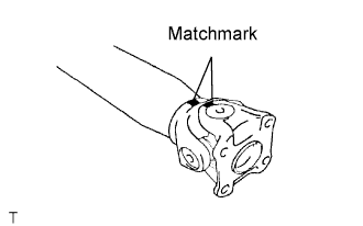 |
Place matchmarks on the flange yoke and sleeve yoke.
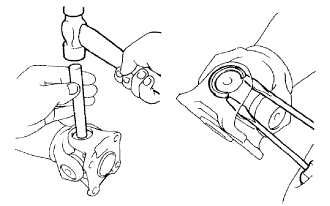 |
Using a brass bar and hammer, slightly tap in the spider bearing outer races.
Using 2 screwdrivers, remove the 4 snap rings from the grooves.
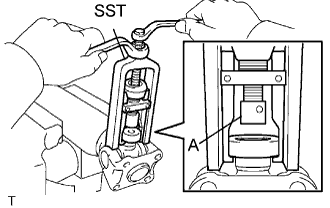 |
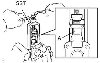
Clamp the propeller shaft in a vise between aluminum plates.
Using SST, push the sleeve yoke side spider bearing until: 1) the spider almost touches the sleeve yoke or propeller shaft, and 2) the spider bearing on the opposite side is partially pushed out.
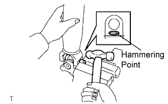 |
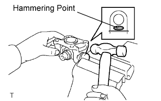
Clamp the pushed out spider bearing outer race in a vise and tap the propeller shaft to remove the spider bearing.
Separate the flange yoke and spider from the propeller shaft.
 |
Reinstall the 2 removed spider bearings to the spider and clamp the spider bearings in a vise.
Using SST, push the flange yoke side spider bearing until: 1) the spider almost touches the flange yoke, and 2) the spider bearing on the opposite side is partially pushed out.
 |
Clamp the pushed out spider bearing outer race in a vise and tap the flange yoke to remove the spider bearing.
Separate the spider from the flange yoke.
