SFI SYSTEM > Fuel Injector Circuit |
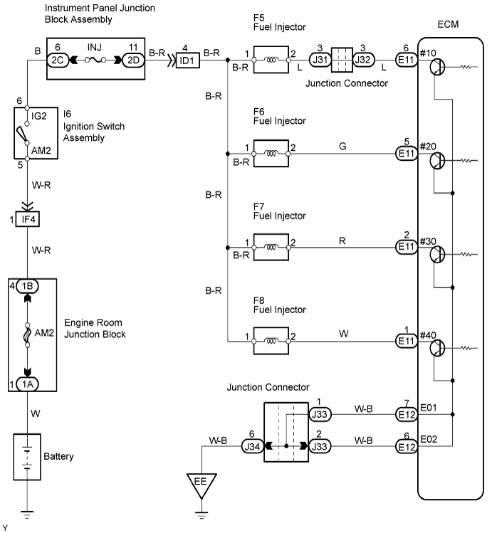
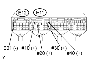
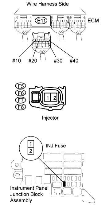
| 1.CHECK ECM (#10, #20, #30, #40 VOLTAGE) |
 |
Turn the ignition switch ON.
Measure the voltage of the ECM connectors.
| Tester Connection | Specified Condition |
| E11-6 (#10) - E12-7 (E01) | 9 to 14 V |
| E11-5 (#20) - E12-7 (E01) | 9 to 14 V |
| E11-2 (#30) - E12-7 (E01) | 9 to 14 V |
| E11-1 (#40) - E12-7 (E01) | 9 to 14 V |
| Tester Connection | Specified Condition |
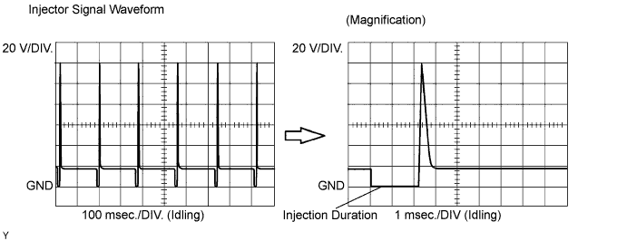
| E11-6 (#10) - E12-7 (E01) | Correct waveform is as shown |
| E11-5 (#20) - E12-7 (E01) | Correct waveform is as shown |
| E11-2 (#30) - E12-7 (E01) | Correct waveform is as shown |
| E11-1 (#40) - E12-7 (E01) | Correct waveform is as shown |
| Tool Setting | Condition |
| 20 V/DIV., 100 or 1 msec./DIV. | Idling |
|
| ||||
| NG | |
| 2.INSPECT FUEL INJECTOR ASSEMBLY (RESISTANCE) |
|
| ||||
| OK | |
| 3.INSPECT FUSE (INJ) |
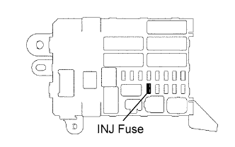 |
Remove the INJ fuse from the instrument panel junction block.
Measure the resistance of the fuse.
|
| ||||
| OK | |
| 4.CHECK WIRE HARNESS OF MISFIRING CYLINDER (INJECTOR - ECM, INJECTOR - INJ FUSE) |
 |
Check the wire harness between the injector and ECM.
Disconnect the F5, F6, F7 and/or F8 injector connectors.
Disconnect the E11 ECM connector.
Measure the resistance of the wire harness side connectors.
| Tester Connection | Specified Condition |
| F5-2 - E11-6 (#10) | Below 1 Ω |
| F6-2 - E11-5 (#20) | Below 1 Ω |
| F7-2 - E11-2 (#30) | Below 1 Ω |
| F8-2 - E11-1 (#40) | Below 1 Ω |
| F5-2 or E11-6 (#10) - Body ground | 10 kΩ or higher |
| F6-2 or E11-5 (#20) - Body ground | 10 kΩ or higher |
| F7-2 or E11-2 (#30) - Body ground | 10 kΩ or higher |
| F8-2 or E11-1 (#40) - Body ground | 10 kΩ or higher |
Check the wire harness between the injector and INJ fuse.
Disconnect the F5, F6, F7 and F8 injector connectors.
Remove the INJ fuse from the instrument panel junction block.
Measure the resistance of the wire harness side connectors.
| Tester Connection | Specified Condition |
| F5-1 - J/B INJ fuse terminal 2 | Below 1 Ω |
| F6-1 - J/B INJ fuse terminal 2 | Below 1 Ω |
| F7-1 - J/B INJ fuse terminal 2 | Below 1 Ω |
| F8-1 - J/B INJ fuse terminal 2 | Below 1 Ω |
| F5-1 or J/B INJ fuse terminal 2 - Body ground | 10 kΩ or higher |
| F6-1 or J/B INJ fuse terminal 2 - Body ground | 10 kΩ or higher |
| F7-1 or J/B INJ fuse terminal 2 - Body ground | 10 kΩ or higher |
| F8-1 or J/B INJ fuse terminal 2 - Body ground | 10 kΩ or higher |
|
| ||||
| OK | |
| 5.CHECK WIRE HARNESS (IGNITION SWITCH - INJ FUSE) |
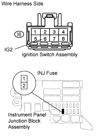 |
Disconnect the I6 ignition switch connector.
Remove the INJ fuse from the instrument panel junction block.
Measure the resistance of the wire harness side connectors.
| Tester Connection | Specified Condition |
| I6-6 (IG2) - J/B INJ fuse terminal 1 | Below 1 Ω |
| I6-6 (IG2) or J/B INJ fuse terminal 1 - Body ground | 10 kΩ or higher |
|
| ||||
| OK | ||
| ||
| 6.CHECK WIRE HARNESS (ECM - BODY GROUND) |
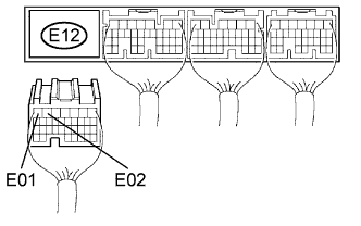 |
Disconnect the E12 ECM connector.
Measure the resistance of the wire harness side connector.
| Tester Connection | Specified Condition |
| E12-7 (E01) - Body ground | Below 1 Ω |
| E12-6 (E02) - Body ground | Below 1 Ω |
|
| ||||
| OK | |
| 7.INSPECT FUEL INJECTOR ASSEMBLY (CHECK FUEL INJECTION VOLUME) |
|
| ||||
| OK | ||
| ||
