SFI SYSTEM > ECM Back-up Power Source Circuit |
| 1.INSPECT FUSE (EFI) |
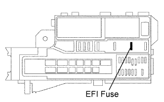 |
Remove the EFI fuse from the engine room junction block.
Measure the resistance of the fuse.
|
| ||||
| OK | |
| 2.CHECK ECM (BATT VOLTAGE) |
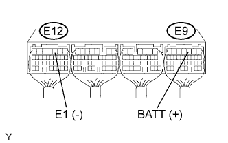 |
Turn the ignition switch ON.
Measure the voltage of the ECM connectors.
| Tester Connection | Specified Condition |
| E9-3 (BATT) - E12-3 (E1) | 8 to 14 V |
|
| ||||
| NG | |
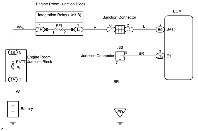
| 3.CHECK WIRE HARNESS (ECM - EFI FUSE, EFI FUSE - BATTERY) |
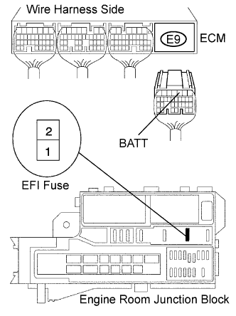 |
Check the wire harness between the EFI fuse and ECM.
Remove the EFI fuse from the engine room junction block.
Disconnect the E9 ECM connector.
Measure the resistance of the wire harness side connectors.
| Tester Connection | Specified Condition |
| J/B EFI fuse terminal 2 - E9-3 (BATT) | Below 1 Ω |
| J/B EFI fuse terminal 2 or E9-3 (BATT) - Body ground | 10 kΩ or higher |
Check the wire harness between the EFI fuse and battery.
Remove the EFI fuse from the engine room junction block.
Disconnect the positive (+) battery cable.
Measure the resistance of the wire harness side connectors.
| Tester Connection | Specified Condition |
| Positive (+) battery cable - J/B EFI fuse terminal 1 | Below 1 Ω |
| Positive (+) battery cable or J/B EFI fuse terminal 1 - Body ground | 10 kΩ or higher |
|
| ||||
| OK | ||
| ||
