SFI SYSTEM > Starter Signal Circuit |
| 1.READ DATA LIST (STA SIGNAL) |
Connect the intelligent tester to the DLC3.
Turn the ignition switch ON and turn the intelligent tester ON.
Enter the following menus: Powertrain / Engine and ECT / Data List / Starter Signal.
Check the result when the ignition switch is turned to ON and START.
| Ignition Switch Position | STA Signal |
| ON | OFF |
| START | ON |
|
| ||||
| NG | |
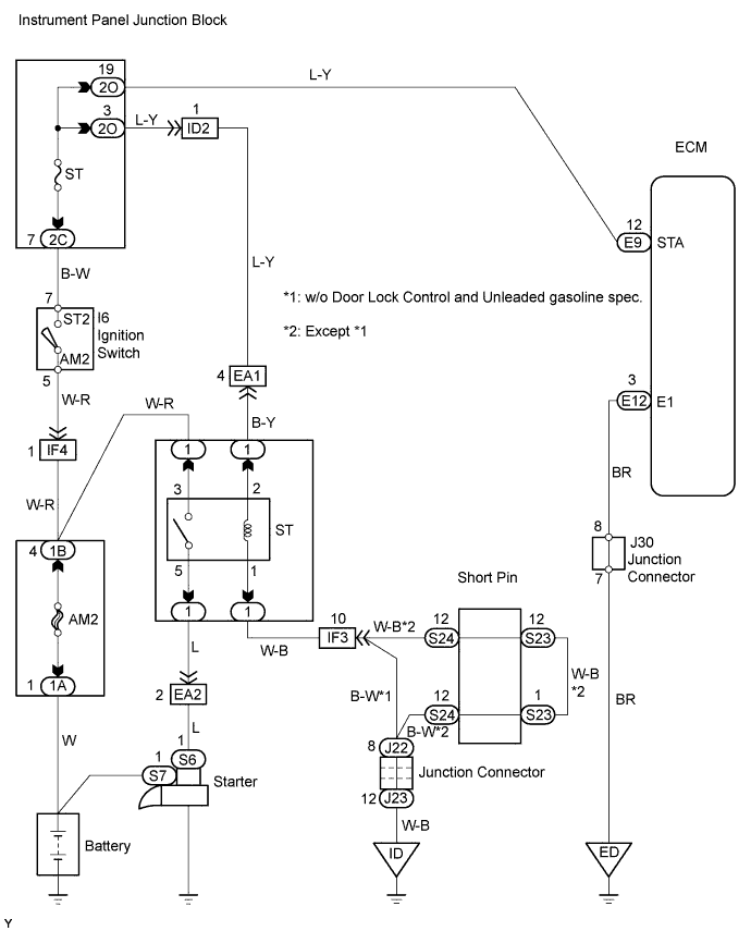
| 2.CHECK WIRE HARNESS (ECM - IGNITION SWITCH) |
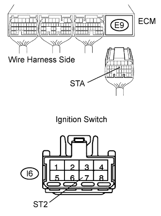 |
Disconnect the E9 ECM connector.
Disconnect the I6 ignition switch connector.
Measure the resistance of the wire harness side connectors.
| Tester Condition | Specified Condition |
| E9-12 (STA) - I6-7 (ST2) | Below 1 Ω |
| E9-12 (STA) or I6-7 (ST2) - Body ground | 10 kΩ or higher |
|
| ||||
| OK | ||
| ||
| 1.CHECK ECM (STA VOLTAGE) |
 |
Turn the ignition switch ON.
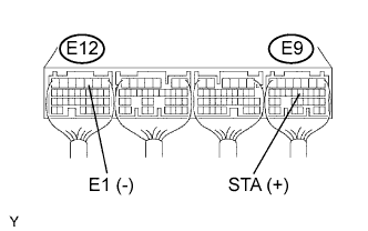
Measure the voltage of the ECM connectors.
| Tester Connection | Specified Condition |
| E9-12 (STA) - E12-3 (E1) | 0 V |
Measure the voltage of the ECM connectors when the engine is cranked.
| Tester Connection | Specified Condition |
| E9-12 (STA) - E12-3 (E1) | 6 V or more |
|
| ||||
| NG | |
| 2.CHECK WIRE HARNESS |
|
Disconnect the E9 ECM connector.
Disconnect the I6 ignition switch connector.
Measure the resistance of the wire harness side connectors.
| Tester Connection | Specified Condition |
| E9-12 (STA) - I6-7 (ST2) | Below 1 Ω |
| E9-12 (STA) or I6-7 (ST2) - Body ground | 10 kΩ or higher |
|
| ||||
| OK | ||
| ||
