DTC P2118/89 Throttle Actuator Control Motor Current Range / Performance |
| DTC No. | DTC Detection Condition | Suspected Area |
| P2118/89 | Open in ETCS power source circuit |
|
| 1.INSPECT FUSE (ETCS) |
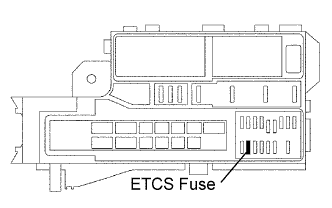 |
Remove the ETCS fuse from the engine room relay block.
Measure the resistance of the fuse.
|
| ||||
| OK | |
| 2.CHECK ECM (+B VOLTAGE) |
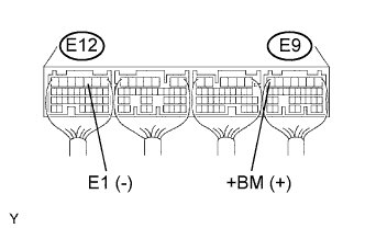 |
Measure the voltage of the ECM connectors.
| Tester Connection | Specified Condition |
| E9-7 (+BM) - E12-3 (E1) | 9 to 14 V |
|
| ||||
| NG | |
| 3.CHECK WIRE HARNESS (ETCS FUSE - ECM AND BATTERY) |
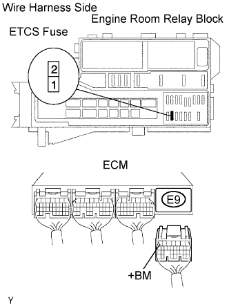 |
Remove the ETCS fuse from the engine room relay block.
Disconnect the E9 ECM connector.
Disconnect the cable from the positive (+) battery terminal.
Measure the resistance of the wire harness side connectors.
| Tester Connection | Specified Condition |
| R/B ETCS fuse terminal 2 - E9-7 (+BM) | Below 1 Ω |
| R/B ETCS fuse terminal 2 or E9-7 (+BM) - Body ground | 10 kΩ or higher |
| Positive (+) battery cable - R/B ETCS fuse terminal 1 | Below 1 Ω |
| Positive (+) battery cable or R/B ETCS fuse terminal 1 - Body ground | 10 kΩ or higher |
|
| ||||
| OK | ||
| ||
