DTC P2120/19 Throttle / Pedal Position Sensor / Switch "D" Circuit |
DTC P2122/19 Throttle / Pedal Position Sensor / Switch "D" Circuit Low Input |
DTC P2123/19 Throttle / Pedal Position Sensor / Switch "D" Circuit High Input |
DTC P2125/19 Throttle / Pedal Position Sensor / Switch "E" Circuit |
DTC P2127/19 Throttle / Pedal Position Sensor / Switch "E" Circuit Low Input |
DTC P2128/19 Throttle / Pedal Position Sensor / Switch "E" Circuit High Input |
DTC P2138/19 Throttle / Pedal Position Sensor / Switch "D" / "E" Voltage Correlation |
| DTC No. | DTC Detection Condition | Suspected Area |
| P2120/19 | VPA1 quickly fluctuates up and down beyond upper and lower malfunction thresholds for 0.5 seconds |
|
| P2122/19 | Condition (a) continues for 0.5 seconds or more when accelerator pedal is fully released:
|
|
| P2123/19 | Condition (a) continues for 2.0 seconds or more:
|
|
| P2125/19 | Condition (a) continues for 0.5 seconds or more:
|
|
| P2127/19 | Condition (a) continues for 0.5 seconds or more when accelerator pedal is fully released:
|
|
| P2128/19 | Conditions (a) and (b) continue for 2.0 seconds or more:
|
|
| P2138/19 | Condition (a) or (b) continues for 2.0 seconds or more:
|
|
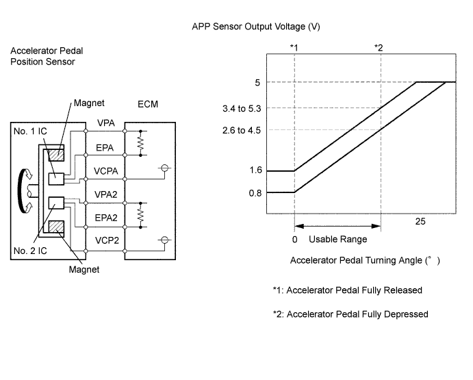
| Suspected Area | Accel Position No.1 When AP Released | Accel Position No.2 When AP Released | Accel Position No.1 When AP Depressed | Accel Position No.2 When AP Depressed |
| VCP circuit open | 0 to 0.2 V | 0 to 0.2 V | 0 to 0.2 V | 0 to 0.2 V |
| Open or ground short in VPA circuit | 0 to 0.2 V | 1.2 to 2.0 V | 0 to 0.2 V | 3.4 to 5.0 V |
| Open or ground short in VPA2 circuit | 0.5 to 1.1 V | 0 to 0.2 V | 2.6 to 4.5 V | 0 to 0.2 V |
| EPA circuit open | 4.5 to 5.0 V | 4.5 to 5.0 V | 4.5 to 5.0 V | 4.5 to 5.0 V |
| 1.READ DATA LIST (ACCELERATOR POSITION NO. 1, ACCELERATOR POSITION NO. 2) |
 |
Connect the intelligent tester to the DLC3.
Turn the ignition switch ON and turn the intelligent tester ON.
Enter the following menus: Powertrain / Engine and ECT / Data List / Accelerator Position No. 1 and Accelerator Position No. 2.
Read the values.
| Accelerator Pedal | Accelerator Position No. 1 | Accelerator Position No. 2 |
| Released | 0.5 to 1.1 V | 1.2 to 2.0 V |
| Depressed | 2.6 to 4.5 V | 3.4 to 5.0 V |
|
| ||||
| NG | |
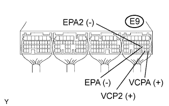
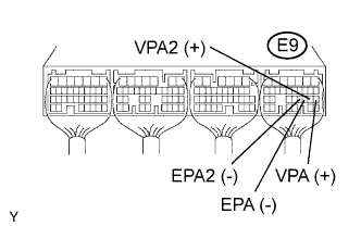
| 2.CHECK ECM (VCPA, VCP2 VOLTAGE) |
 |
Turn the ignition switch ON.
Measure the voltage of the ECM connector.
| Tester Connection | Specified Condition |
| E9-26 (VCPA) - E9-20 (EPA) | 4.5 to 5.0 V |
| E9-27 (VCP2) - E9-21 (EPA2) | 4.5 to 5.0 V |
|
| ||||
| OK | |
| 3.CHECK ECM (VPA, VPA2 VOLTAGE) |
 |
Turn the ignition switch ON.
Measure the voltage of the ECM connector.
| Tester Connection | Accelerator Pedal Condition | Specified Condition |
| E9-18 (VPA) - E9-20 (EPA) | Released | 0.5 to 1.1 V |
| E9-18 (VPA) - E9-20 (EPA) | Depressed | 2.5 to 4.6 V |
| E9-19 (VPA2) - E9-21 (EPA2) | Released | 1.5 to 2.9 V |
| E9-19 (VPA2) - E9-21 (EPA2) | Depressed | 3.5 to 5.0 V |
|
| ||||
| NG | |
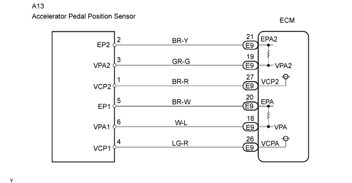
| 4.CHECK WIRE HARNESS (ACCELERATOR PEDAL POSITION SENSOR - ECM) |
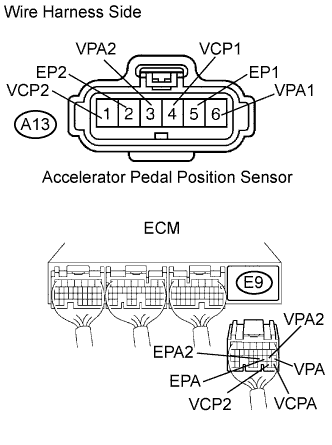 |
Disconnect the A13 accelerator pedal position sensor connector.
Disconnect the E9 ECM connector.
Measure the resistance of the wire harness side connectors.
| Tester Connection | Specified Condition |
| A13-6 (VPA1) - E9-18 (VPA) | Below 1 Ω |
| A13-5 (EP1) - E9-20 (EPA) | Below 1 Ω |
| A13-4 (VCP1) - E9-26 (VCPA) | Below 1 Ω |
| A13-3 (VPA2) - E9-19 (VPA2) | Below 1 Ω |
| A13-2 (EP2) - E9-21 (EPA2) | Below 1 Ω |
| A13-1 (VCP2) - E9-27 (VCP2) | Below 1 Ω |
| A13-6 (VPA1) or E9-18 (VPA) - Body ground | 10 kΩ or higher |
| A13-5 (EP1) or E9-20 (EPA) - Body ground | 10 kΩ or higher |
| A13-4 (VCP1) or E9-26 (VCPA) - Body ground | 10 kΩ or higher |
| A13-3 (VPA2) or E9-19 (VPA2) - Body ground | 10 kΩ or higher |
| A13-2 (EP2) or E9-21 (EPA2) - Body ground | 10 kΩ or higher |
| A13-1 (VCP2) or E9-27 (VCP2) - Body ground | 10 kΩ or higher |
|
| ||||
| OK | |
| 5.REPLACE ACCELERATOR PEDAL ROD |
| NEXT | |
| 6.CHECK IF DTC OUTPUT RECURS (ACCELERATOR PEDAL POSITION SENSOR DTCS) |
Connect the intelligent tester to the DLC3.
Turn the ignition switch ON and turn the intelligent tester ON.
Clear the DTCs (Click here).
Start the engine.
Idle the engine for 15 seconds or more.
Enter the following menus: Powertrain / Engine and ECT / DTC.
Read DTC (Click here).
| Display (DTC Output) | Proceed to |
| One or more of P2120/19, P2122/19, P2123/19, P2125/19, P2127/19, P2128/19 and P2138/19 | A |
| No output | B |
|
| ||||
| A | ||
| ||
| 1.CHECK ECM (VCPA, VCP2 VOLTAGE) |
|
Turn the ignition switch ON.
Measure the voltage of the ECM connector.
| Tester Connection | Specified Condition |
| E9-26 (VCPA) - E9-20 (EPA) | 4.5 to 5.0 V |
| E9-27 (VCP2) - E9-21 (EPA2) | 4.5 to 5.0 V |
|
| ||||
| OK | |
| 2.CHECK ECM (VPA, VPA2 VOLTAGE) |
|
Turn the ignition switch ON.
Measure the voltage of the ECM connector.
| Tester Connection | Accelerator Pedal Condition | Specified Condition |
| E9-18 (VPA) - E9-20 (EPA) | Released | 0.5 to 1.1 V |
| E9-18 (VPA) - E9-20 (EPA) | Depressed | 2.5 to 4.6 V |
| E9-19 (VPA2) - E9-21 (EPA2) | Released | 1.5 to 2.9 V |
| E9-19 (VPA2) - E9-21 (EPA2) | Depressed | 3.5 to 5.0 V |
|
| ||||
| NG | |
| 3.CHECK WIRE HARNESS (ACCELERATOR PEDAL POSITION SENSOR - ECM) |
|
Disconnect the A13 accelerator pedal position sensor connector.
Disconnect the E9 ECM connector.
Measure the resistance of the wire harness side connectors.
| Tester Connection | Specified Condition |
| A13-6 (VPA1) - E9-18 (VPA) | Below 1 Ω |
| A13-5 (EP1) - E9-20 (EPA) | Below 1 Ω |
| A13-4 (VCP1) - E9-26 (VCPA) | Below 1 Ω |
| A13-3 (VPA2) - E9-19 (VPA2) | Below 1 Ω |
| A13-2 (EP2) - E9-21 (EPA2) | Below 1 Ω |
| A13-1 (VCP2) - E9-27 (VCP2) | Below 1 Ω |
| A13-6 (VPA1) or E9-18 (VPA) - Body ground | 10 kΩ or higher |
| A13-5 (EP1) or E9-20 (EPA) - Body ground | 10 kΩ or higher |
| A13-4 (VCP1) or E9-26 (VCPA) - Body ground | 10 kΩ or higher |
| A13-3 (VPA2) or E9-19 (VPA2) - Body ground | 10 kΩ or higher |
| A13-2 (EP2) or E9-21 (EPA2) - Body ground | 10 kΩ or higher |
| A13-1 (VCP2) or E9-27 (VCP2) - Body ground | 10 kΩ or higher |
|
| ||||
| OK | |
| 4.REPLACE ACCELERATOR PEDAL ROD |
| NEXT | |
| 5.CHECK IF DTC OUTPUT RECURS (ACCELERATOR PEDAL POSITION SENSOR DTCS) |
Clear the DTCs (Click here).
Start the engine.
Idle the engine for 15 seconds or more.
Read DTC (Click here).
| Display (DTC Output) | Proceed to |
| One or more of P2120/19, P2122/19, P2123/19, P2125/19, P2127/19, P2128/19 and P2138/19 | A |
| No output | B |
|
| ||||
| A | ||
| ||
