DTC P2102/41 Throttle Actuator Control Motor Circuit Low |
DTC P2103/41 Throttle Actuator Control Motor Circuit High |
| DTC No. | DTC Detection Condition | Suspected Area |
| P2102/41 | Conditions (a) and (b) continue for 2.0 seconds (1 trip detection logic):
|
|
| P2103/41 | Either of following conditions is met (1 trip detection logic):
|
|
| 1.INSPECT THROTTLE BODY ASSEMBLY (RESISTANCE OF THROTTLE ACTUATOR) |
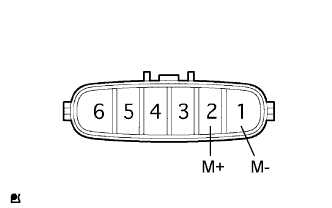 |
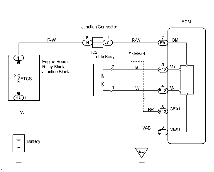
Disconnect the T25 throttle body connector.
Measure the resistance of the throttle actuator.
| Tester Connection | Specified Condition |
| 2 (M+) - 1 (M-) | 0.3 to 100 Ωat 20°C (68°F) |
|
| ||||
| OK | |
| 2.CHECK WIRE HARNESS (THROTTLE ACTUATOR - ECM) |
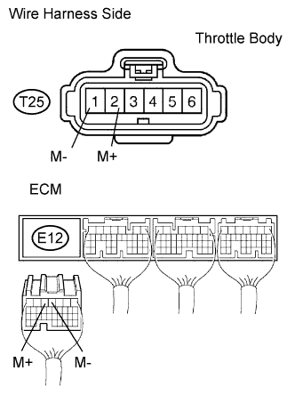 |
Disconnect the T25 throttle body connector.
Disconnect the E12 ECM connector.
Measure the resistance of the wire harness side connectors.
| Tester Connection | Specified Condition |
| T25-2 (M+) - E12-5 (M+) | Below 1 Ω |
| T25-1 (M-) - E12-4 (M-) | Below 1 Ω |
| T25-2 (M+) or E12-5 (M+) - Body ground | 10 kΩ or higher |
| T25-1 (M-) or E12-4 (M-) - Body ground | 10 kΩ or higher |
|
| ||||
| OK | |
| 3.INSPECT THROTTLE BODY ASSEMBLY |
Visually check for foreign objects between the throttle valve and housing.
Also, check that the valve can open and close smoothly.
|
| ||||
| OK | ||
| ||
