SFI SYSTEM > Fuel Pump Control Circuit |
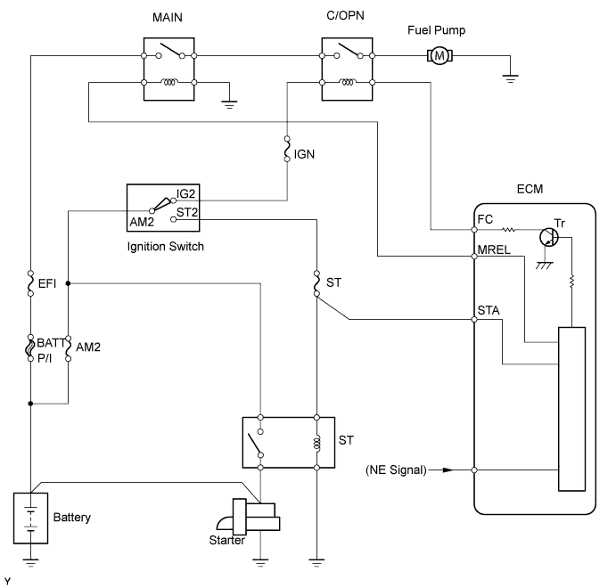
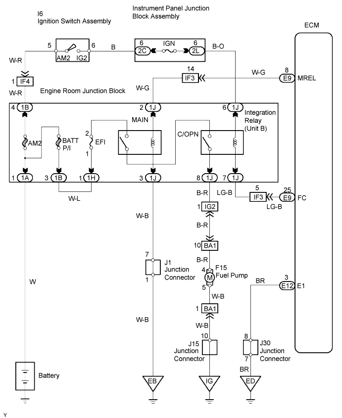
| 1.PERFORM ACTIVE TEST (OPERATE C/OPN RELAY) |
Connect the intelligent tester to the DLC3.
Turn the ignition switch ON and turn the intelligent tester ON.
Enter the following menus: Powertrain / Engine and ECT / Active Test / Fuel Pump.
Check the operation of the relay while operating it using the intelligent tester.
|
| ||||
| NG | |
| 2.CHECK ECM POWER SOURCE CIRCUIT |
Refer to ECM power source circuit (Click here).
|
| ||||
| OK | |
| 3.CHECK ECM (FC VOLTAGE) |
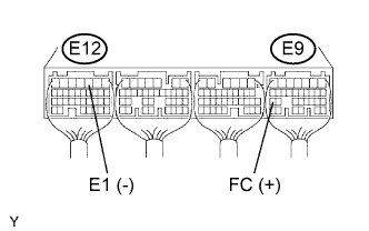 |
Turn the ignition switch ON.
Measure the voltage of the ECM connectors.
| Tester Connection | Specified Condition |
| E9-25 (FC) - E12-3 (E1) | 9 to 14 V |
|
| ||||
| NG | |
| 4.CHECK INTEGRATION RELAY (C/OPN RELAY) |
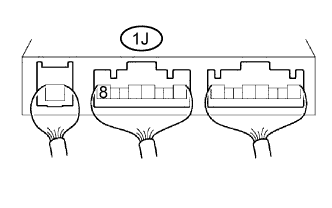 |
Remove the integration relay from the engine room junction block (Click here).
Measure the voltage of the C/OPN relay.
| Terminal Connection | Condition | Specified Condition |
| 1J-8 - Body ground | Ignition switch ON | 10 to 14 V |
|
| ||||
| OK | |
| 5.CHECK WIRE HARNESS (C/OPN RELAY - ECM) |
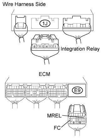 |
Disconnect the 1J integration relay connector from the engine room junction block (Click here).
Disconnect the E9 ECM connector.
Measure the resistance of the wire harness side connectors.
| Tester Connection | Specified Condition |
| 1J-2 - E9-8 (MREL) | Below 1 Ω |
| 1J-7 - E9-25 (FC) | Below 1 Ω |
| 1J-2 or E9-8 (MREL) - Body ground | 10 kΩ or higher |
| 1J-7 or E9-25 (FC) - Body ground | 10 kΩ or higher |
|
| ||||
| OK | ||
| ||
| 6.INSPECT FUEL PUMP |
Inspect the fuel pump (Click here).
|
| ||||
| OK | |
| 7.CHECK WIRE HARNESS (C/OPN RELAY - FUEL PUMP, FUEL PUMP - BODY GROUND) |
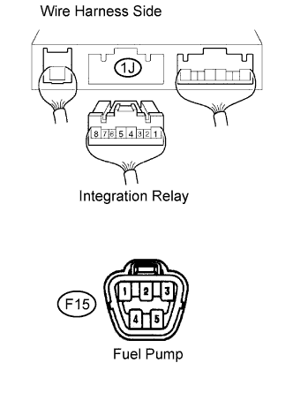 |
Disconnect the 1J integration relay connector from the engine room junction block (Click here).
Disconnect the F15 fuel pump connector.
Measure the resistance of the wire harness side connectors.
| Tester Connection | Specified Condition |
| 1J-8 - F15-4 | Below 1 Ω |
| F15-5 - Body ground | Below 1 Ω |
| 1J-8 or F15-4 - Body ground | 10 kΩ or higher |
|
| ||||
| OK | ||
| ||
| 1.INSPECT OPERATION OF FUEL PUMP |
Operation of fuel pump (Click here).
|
| ||||
| NG | |
| 2.CHECK ECM POWER SOURCE CIRCUIT |
Refer to ECM power source circuit (Click here).
|
| ||||
| OK | |
| 3.CHECK ECM (FC VOLTAGE) |
|
Turn the ignition switch ON.
Measure the voltage of the ECM connectors.
| Tester Connection | Specified Condition |
| E9-25 (FC) - E12-3 (E1) | 9 to 14 V |
|
| ||||
| NG | |
| 4.CHECK INTEGRATION RELAY (C/OPN RELAY) |
|
Remove the integration relay from the engine room junction block (Click here).
Measure the voltage of the C/OPN relay.
| Tester Connection | Condition | Specified Condition |
| 1J-8 - Body ground | Ignition switch ON | 10 to 14 V |
|
| ||||
| OK | |
| 5.CHECK WIRE HARNESS (C/OPN RELAY - ECM) |
|
Disconnect the 1J integration relay connector from the engine room junction block (Click here).
Disconnect the E9 ECM connector.
Measure the resistance of the wire harness side connectors.
| Tester Connection | Specified Condition |
| 1J-2 - E9-8 (MREL) | Below 1 Ω |
| 1J-7 - E9-25 (FC) | Below 1 Ω |
| 1J-2 or E9-8 (MREL) - Body ground | 10 kΩ or higher |
| 1J-7 or E9-25 (FC) - Body ground | 10 kΩ or higher |
|
| ||||
| OK | ||
| ||
| 6.INSPECT FUEL PUMP |
Inspect the fuel pump (Click here).
|
| ||||
| OK | |
| 7.CHECK WIRE HARNESS (C/OPN RELAY - FUEL PUMP, FUEL PUMP - BODY GROUND) |
|
Disconnect the 1J integration relay connector from the engine room junction block (Click here).
Disconnect the F15 fuel pump connector.
Measure the resistance of the wire harness side connectors.
| Tester Connection | Specified Condition |
| 1J-8 - F15-4 | Below 1 Ω |
| F15-5 - Body ground | Below 1 Ω |
| 1J-8 or F15-4 - Body ground | 10 kΩ or higher |
|
| ||||
| OK | ||
| ||
