DTC P0327/52 Knock Sensor 1 Circuit Low Input (Bank 1 or Single Sensor) |
DTC P0328/52 Knock Sensor 1 Circuit High Input (Bank 1 or Single Sensor) |
| DTC No. | DTC Detection Condition | Suspected Area |
| P0327/52 | Output voltage of the knock sensor is 0.5 V or less |
|
| P0328/52 | Output voltage of the knock sensor is 4.5 V or more |
|
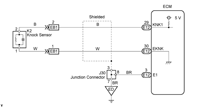
| 1.CHECK WIRE HARNESS (ECM - KNOCK SENSOR) |
 |
Disconnect the E12 ECM connector.
Measure the resistance of the wire harness side connector.
| Tester Connection | Condition | Specified Condition |
| E12-29 (KNK1) - E12-30 (EKNK) | 20°C (68°F) | 120 to 280 kΩ |
|
| ||||
| OK | |
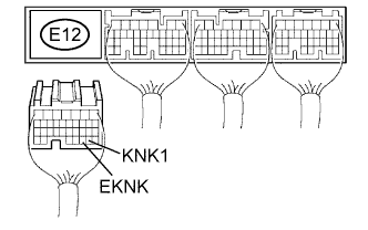
| 2.CHECK ECM (KNK1 VOLTAGE) |
 |
Turn the ignition switch ON.
Measure the voltage of the ECM connector.
| Tester Connection | Specified Condition |
| E12-29 (KNK1) - E12-30 (EKNK) | 4.5 to 5.5 V |
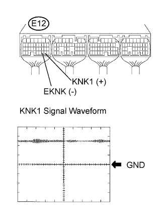
| Tester Connection | Specified Condition |
| E12-29 (KNK1) - E12-30 (EKNK) | Correct waveform is as shown |
| Tool Setting | Condition |
| 0.01 to 10 V/DIV., 0.01 to 10 msec./DIV. | After warming up engine, keep engine speed at 4,000 rpm |
|
| ||||
| OK | ||
| ||
| 3.INSPECT KNOCK SENSOR |
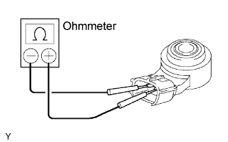 |
Remove the sensor.
Measure the resistance of the sensor.
| Tester Connection | Condition | Specified Condition |
| 1 - 2 | 20°C (68°F) | 120 to 280 kΩ |
|
| ||||
| OK | ||
| ||
