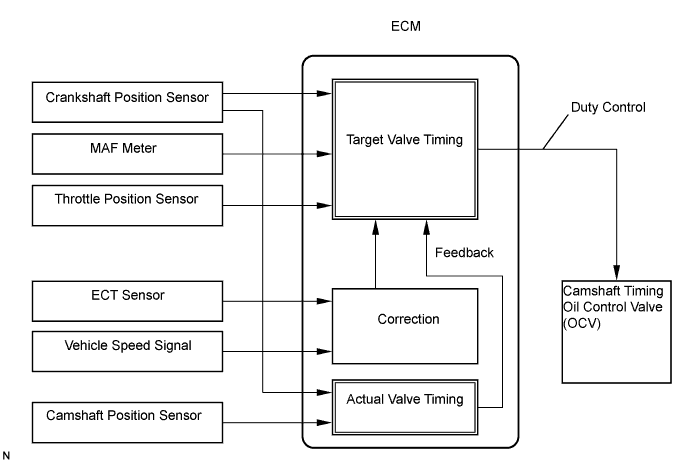
DTC P0010/39 Camshaft Position "A" Actuator Circuit (Bank 1) |
| DTC No. | DTC Detection Condition | Suspected Area |
| P0010/39 | Open or short in oil control valve circuit (1 trip detection logic) |
|
| 1.PERFORM ACTIVE TEST (OPERATE OCV) |
Start and warm up the engine.
Turn the ignition switch OFF.
Connect the intelligent tester to the DLC3.
Turn the ignition switch ON and turn the intelligent tester ON.
Enter the following menus: Powertrain / Engine and ECT / Active Test / Activate the VVT System (Bank 1).
Using the intelligent tester, operate the OCV and check the engine speed.
| Tester Operation | Specified Condition |
| OCV is OFF | Normal engine speed |
| OCV is ON | Rough idle or engine stall |
|
| ||||
| NG | |
| 2.CHECK CAMSHAFT TIMING OIL CONTROL VALVE ASSEMBLY (OCV SIGNAL) |
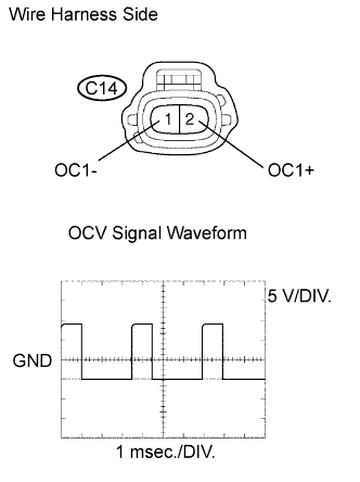 |
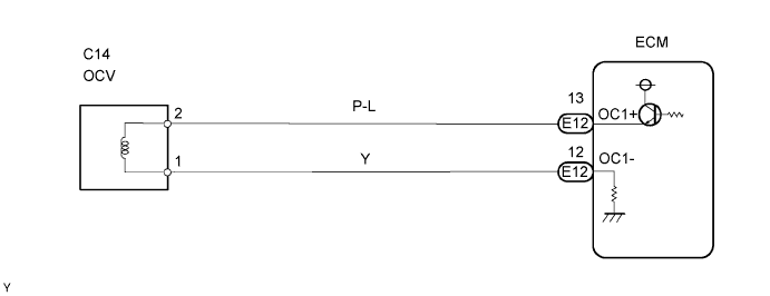
Disconnect the C14 OCV connector.
While idling the engine, check the waveform of the OCV connector using the oscilloscope.
| Tester Connection | Specified Condition |
| C14-2 (OC1+) - C14-1 (OC1-) | Correct waveform is as shown |
| Tool Setting | Condition |
| 5 V/DIV., 1 msec./DIV. | Accelerate slowly after engine warm-up |
|
| ||||
| NG | |
| 3.CHECK ECM (OCV SIGNAL) |
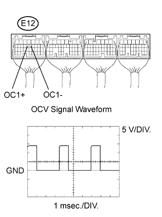 |
While idling the engine, check the waveform of the ECM connector using the oscilloscope.
| Tester Connection | Specified Condition |
| E12-13 (OC1+) - E12-12 (OC1-) | Correct waveform is as shown |
| Tool Setting | Condition |
| 5 V/DIV., 1 msec./DIV. | Accelerate slowly after engine warm-up |
|
| ||||
| OK | ||
| ||
| 1.CHECK CAMSHAFT TIMING OIL CONTROL VALVE ASSEMBLY (OPERATE OCV) |
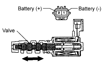 |
Disconnect the C14 OCV connector.
Apply positive (+) battery voltage between the terminals of the OCV.
Check the engine speed.
|
| ||||
| OK | |
| 2.CHECK ECM (OCV SIGNAL) |
|
While idling the engine, check the waveform of the ECM connector using the oscilloscope.
| Tester Connection | Specified Condition |
| E12-13 (OC1+) - E12-12 (OC1-) | Correct waveform is as shown |
| Tool Setting | Condition |
| 5 V/DIV., 1 msec./DIV. | Accelerate slowly after engine warm-up |
|
| ||||
| OK | |
| 3.CHECK WIRE HARNESS (CAMSHAFT TIMING OIL CONTROL VALVE (OCV) - ECM) |
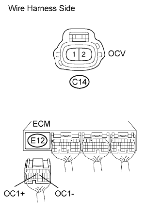 |
Disconnect the C14 OCV connector.
Disconnect the E12 ECM connector.
Measure the resistance of the wire harness side connectors.
| Tester Connection | Specified Condition |
| C14-2 - E12-13 (OC1+) | Below 1 Ω |
| C14-1 - E12-12 (OC1-) | Below 1 Ω |
| C14-2 or E12-13 (OC1+) - Body ground | 10 kΩ or higher |
| C14-1 or E12-12 (OC1-) - Body ground | 10 kΩ or higher |
|
| ||||
| OK | ||
| ||
