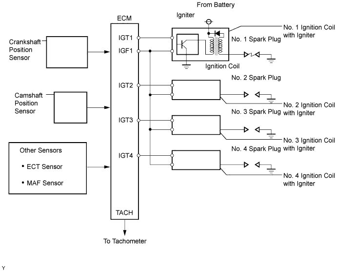
DTC P0351/14 Ignition Coil "A" Primary / Secondary Circuit |
DTC P0352/15 Ignition Coil "B" Primary / Secondary Circuit |
DTC P0353/14 Ignition Coil "C" Primary / Secondary Circuit |
DTC P0354/15 Ignition Coil "D" Primary / Secondary Circuit |
| DTC No. | DTC Detection Condition | Trouble Area |
| P0351/14 P0352/15 P0353/14 P0354/15 | No IGF signal to ECM while engine is running |
|
| 1.PERFORM SIMULATION TEST |
Clear the DTCs (Click here).
Change the arrangement of the ignition coils (with igniters).
Perform the simulation test.
| Display (DTC Output) | Proceed to |
| Cleared DTCs are output again | A |
| Other DTCs | B |
|
| ||||
| A | |
| 2.INSPECT IGNITION COIL ASSEMBLY (POWER SOURCE) |
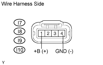 |
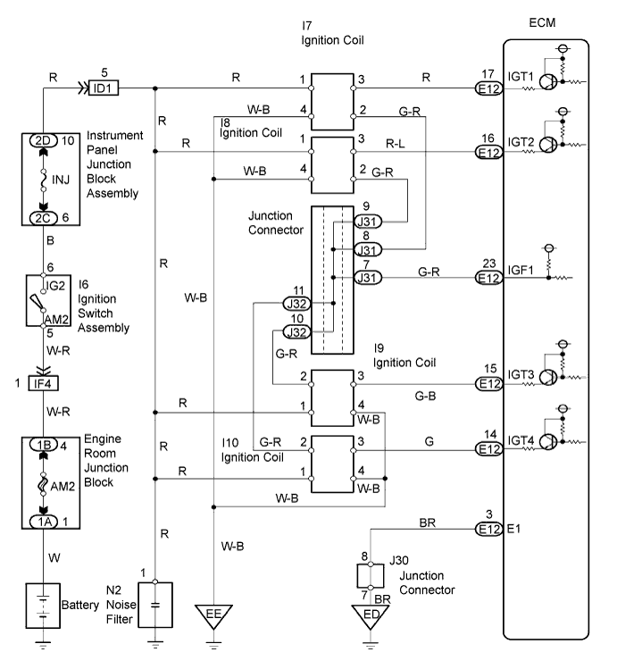
Disconnect the I7, I8, I9 and I10 ignition coil with igniter connectors.
Measure the resistance of the wire harness side connectors.
| Tester Connection | Specified Condition |
| I7-4 (GND) - Body ground | Below 1 Ω |
| I8-4 (GND) - Body ground | Below 1 Ω |
| I9-4 (GND) - Body ground | Below 1 Ω |
| I10-4 (GND) - Body ground | Below 1 Ω |
Turn the ignition switch ON.
Measure the voltage of the wire harness side connectors.
| Tester Connection | Specified Condition |
| I7-1 (+B) - I7-4 (GND) | 9 to 14 V |
| I8-1 (+B) - I8-4 (GND) | 9 to 14 V |
| I9-1 (+B) - I9-4 (GND) | 9 to 14 V |
| I10-1 (+B) - I10-4 (GND) | 9 to 14 V |
|
| ||||
| NG | |
| 3.CHECK WIRE HARNESS (IGNITION COIL ASSEMBLY - ECM) |
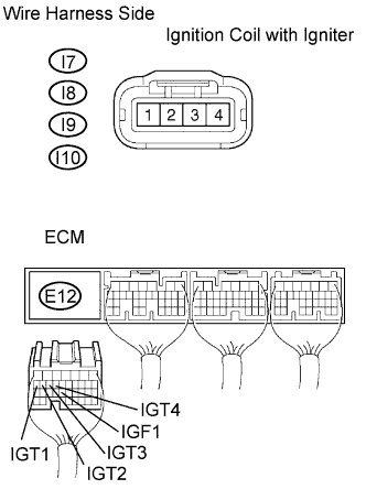 |
Disconnect the I7, I8, I9 and I10 ignition coil with igniter connectors.
Disconnect the E12 ECM connector.
Measure the resistance of the wire harness side connectors.
| Tester Connection | Specified Condition |
| I7-2 - E12-23 (IGF1) | Below 1 Ω |
| I8-2 - E12-23 (IGF1) | Below 1 Ω |
| I9-2 - E12-23 (IGF1) | Below 1 Ω |
| I10-2 - E12-23 (IGF1) | Below 1 Ω |
| I7-3 - E12-17 (IGT1) | Below 1 Ω |
| I8-3 - E12-16 (IGT2) | Below 1 Ω |
| I9-3 - E12-15 (IGT3) | Below 1 Ω |
| I10-3 - E12-14 (IGT4) | Below 1 Ω |
| I7-2 or E12-23 (IGF1) - Body ground | 10 kΩ or higher |
| I8-2 or E12-23 (IGF1) - Body ground | 10 kΩ or higher |
| I9-2 or E12-23 (IGF1) - Body ground | 10 kΩ or higher |
| I10-2 or E12-23 (IGF1) - Body ground | 10 kΩ or higher |
| I7-3 or E12-17 (IGT1) - Body ground | 10 kΩ or higher |
| I8-3 or E12-16 (IGT2) - Body ground | 10 kΩ or higher |
| I9-3 or E12-15 (IGT3) - Body ground | 10 kΩ or higher |
| I10-3 or E12-14 (IGT4) - Body ground | 10 kΩ or higher |
|
| ||||
| OK | |
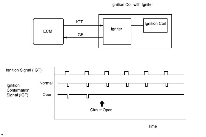
| 4.CHECK ECM (IGT1, IGT2, IGT3, IGT4, IGF1 SIGNAL) |
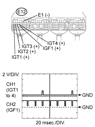 |
While cranking or idling, check the waveform of the ECM connector using the oscilloscope.
| Tester Connection | Specified Condition |
| E12-17 (IGT1) - E12-3 (E1) | Correct waveform is as shown |
| E12-16 (IGT2) - E12-3 (E1) | Correct waveform is as shown |
| E12-15 (IGT3) - E12-3 (E1) | Correct waveform is as shown |
| E12-14 (IGT4) - E12-3 (E1) | Correct waveform is as shown |
| E12-23 (IGF1) - E12-3 (E1) | Correct waveform is as shown |
| Tool Setting | Condition |
| 2 V/DIV., 20 msec./DIV. | Idling |
|
| ||||
| OK | |
| 5.CHECK IF DTC OUTPUT RECURS (IGNITION COIL ASSEMBLY - INJ FUSE) |
Clear the DTC (Click here).
Connect the intelligent tester to the DLC3.
Turn the ignition switch ON and turn the intelligent tester ON.
Enter the following menus: Powertrain / Engine and ECT / DTC.
Read the DTC.
| Display (DTC Output) | Proceed to |
| One or more of P0351, P0352, P0353, P0354, P0355 and P0356 | A |
| No output | B |
|
| ||||
| A | ||
| ||
