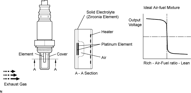
DTC P0130/21 Oxygen (A/F) Sensor Circuit Malfunction (Bank 1 Sensor 1) |
| DTC No. | DTC Detection Condition | Trouble Area |
| P0130/21 | Heated oxygen sensor output voltage is less than 0.45 V for 75 seconds or more |
|
| 1.CHECK OTHER DTC OUTPUT |
Connect the intelligent tester to the DLC3.
Enter the following menus: Powertrain / Engine and ECT / DTC.
Read the DTCs.
| DTC | Proceed to |
| Only P0130/21 is output | A |
| Other DTCs are output besides P0130/21 | B |
|
| ||||
| A | |
| 2.READ VALUE OF DATA LIST (OUTPUT VOLTAGE OF HEATED OXYGEN SENSOR) |
Connect the intelligent tester to the DLC3.
Start the engine and turn the intelligent tester ON.
Enter the following menus: Powertrain / Engine and ECT / Data List / O2S B1 S1.
Warm up the heated oxygen sensor at an engine speed of 2,500 rpm for approximately 90 seconds.
Read the output voltage of the heated oxygen sensor during engine idling.
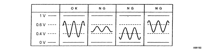
|
| ||||
| NG | |
| 3.CHECK PCV HOSE |
|
| ||||
| OK | |
| 4.INSPECT HEATED OXYGEN SENSOR |
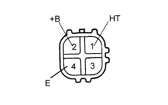 |
Disconnect the H6 sensor connector.
Measure the resistance of the sensor.
| Tester Connection | Condition | Specified Condition |
| 1 (HT) - 2 (+B) | 20°C (68°F) | 5 to 10 Ω |
| 1 (HT) - 4 (E) | - | 10 kΩ or higher |
|
| ||||
| OK | |
| 5.INSPECT INTEGRATION RELAY (MAIN RELAY) |
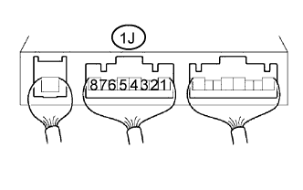 |
Remove the integration relay from the engine room junction block (Click here).
Measure the voltage of the MAIN relay.
| Tester Connection | Condition | Specified Condition |
| 1J-5 - Body ground | Ignition switch ON | 10 to 14 V |
|
| ||||
| OK | |
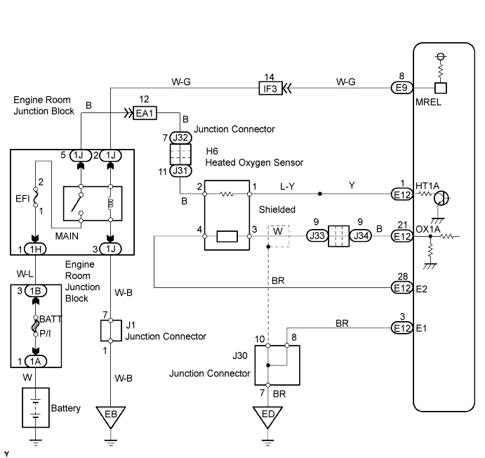
| 6.CHECK WIRE HARNESS (HEATED OXYGEN SENSOR - ECM) |
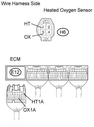 |
Disconnect the H6 heated oxygen sensor connector.
Disconnect the E12 ECM connector.
Measure the resistance of the wire harness side connectors.
| Tester Connection | Specified Condition |
| H6-1 (HT) - E12-1 (HT1A) H6-3 (OX) - E12-21 (OX1A) | Below 1 Ω |
| H6-1 (HT) or E12-1 (HT1A) - Body ground H6-3 (OX) or E12-21 (OX1A) - Body ground | 10 kΩ or higher |
|
| ||||
| OK | |
| 7.CHECK AIR INDUCTION SYSTEM |
Check the air induction system for vacuum leakage.
|
| ||||
| OK | |
| 8.CHECK FUEL PRESSURE |
|
| ||||
| OK | |
| 9.INSPECT FUEL INJECTOR ASSEMBLY |
|
| ||||
| OK | ||
| ||
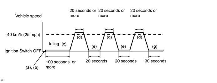
| 10.PERFORM CONFIRMATION DRIVING PATTERN |
| NEXT | |
| 11.READ OUTPUT DTC |
Read the DTC using the intelligent tester.
| DTC | Proceed to |
| Only P0130/21 is output | A |
| Other DTCs are output besides P0130/21 | B |
|
| ||||
| A | ||
| ||
| 1.CHECK OTHER DTC OUTPUT |
| DTC | Proceed to |
| Only P0130/21 is output | A |
| Other DTCs are output besides P0130/21 | B |
|
| ||||
| A | |
| 2.CHECK WIRE HARNESS (HEATED OXYGEN SENSOR - ECM) |
|
Disconnect the H6 heated oxygen sensor connector.
Disconnect the E12 ECM connector.
Measure the resistance of the wire harness side connectors.
| Tester Connection | Specified Condition |
| H6-1 (HT) - E12-1 (HT1A) H6-3 (OX) - E12-21 (OX1A) | Below 1 Ω |
| H6-1 (HT) or E12-1 (HT1A) - Body ground H6-3 (OX) or E12-21 (OX1A) - Body ground | 10 kΩ or higher |
|
| ||||
| OK | ||
| ||
