DTC P0100/31 Mass Air Flow Circuit Malfunction |
DTC P0102/31 Mass or Volume Air Flow Circuit Low Input |
DTC P0103/31 Mass or Volume Air Flow Circuit High Input |
| DTC No. | DTC Detection Condition | Suspected Area |
| P0100/31 | When the MAF meter circuit is open or short for more than 3 seconds |
|
| P0102/31 | When the MAF meter circuit is open for more than 3 seconds |
|
| P0103/31 | When the MAF meter circuit is shorted for more than 3 seconds |
|
| Air Flow Value (gm/second) | Malfunction |
| Approximately 0 |
|
| 271.0 or more | Open in EVG circuit |
| 1.READ DATA LIST (MASS AIR FLOW RATE) |
Connect the intelligent tester to the DLC3.
Start the engine.
Turn the intelligent tester ON.
Enter the following menus: Powertrain / Engine and ECT / Data List / MAF.
Read the values.
| Mass Air Flow Rate (g/second) | Proceed to |
| 0.0 | A |
| 271.0 or more | B |
| Between 1.0 and 270.0* | C |
|
| ||||
|
| ||||
| A | |
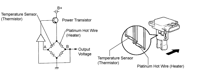
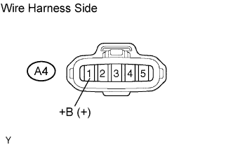
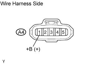
| 2.CHECK MASS AIR FLOW METER (POWER SOURCE) |
 |
Disconnect the A4 MAF meter connector.
Turn the ignition switch ON.
Measure the voltage of the wire harness side connector.
| Tester Connection | Specified Condition |
| A4-1 (+B) - Body ground | 9 to 14 V |
|
| ||||
| OK | |
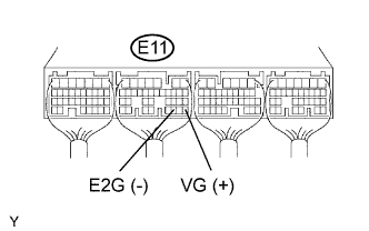
| 3.CHECK ECM (VG VOLTAGE) |
 |
Start the engine.
Measure the voltage of the ECM connector.
| Tester Connection | Condition | Specified Condition |
| E11-28 (VG) - E11-30 (E2G) | Engine is idling | 0.5 to 3.0 V |
|
| ||||
| NG | |
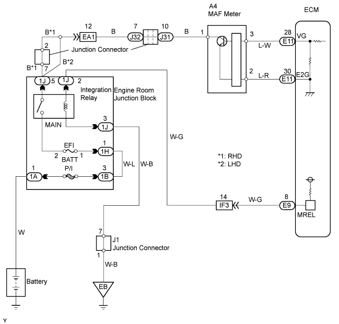
| 4.CHECK WIRE HARNESS (MASS AIR FLOW METER - ECM) |
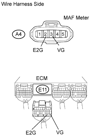 |
Disconnect the A4 MAF meter connector.
Disconnect the E11 ECM connector.
Measure the resistance of the wire harness side connectors.
| Tester Connection | Specified Condition |
| A4-3 (VG) - E11-28 (VG) | Below 1 Ω |
| A4-2 (E2G) - E11-30 (E2G) | Below 1 Ω |
| A4-3 (VG) or E11-28 (VG) - Body ground | 10 kΩ or higher |
|
| ||||
| OK | ||
| ||
| 5.CHECK WIRE HARNESS (MASS AIR FLOW METER - MAIN RELAY) |
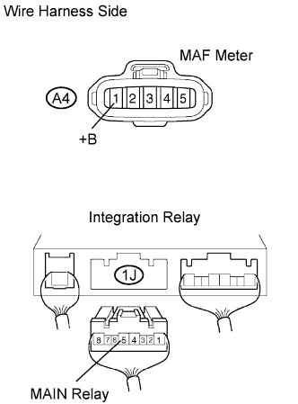 |
Disconnect the A4 MAF meter connector.
Disconnect the 1J integration relay connector from the engine room junction block (Click here).
Measure the resistance of the wire harness side connectors.
| Tester Connection | Specified Condition |
| A4-1 (+B) - 1J-5 | Below 1 Ω |
| A4-1 (+B) or 1J-5 - Body ground | 10 kΩ or higher |
|
| ||||
| OK | ||
| ||
| 6.CHECK ECM (SENSOR GROUND) |
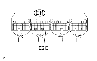 |
Measure the resistance of the E11 ECM connector.
| Tester Connection | Specified Condition |
| E11-30 (E2G) - Body ground | Below 1Ω |
|
| ||||
| OK | |
| 7.CHECK WIRE HARNESS (MASS AIR FLOW METER - ECM) |
|
Disconnect the A4 MAF meter connector.
Disconnect the E11 ECM connector.
Measure the resistance of the wire harness side connectors.
| Tester Connection | Specified Condition |
| A4-3 (VG) - E11-28 (VG) | Below 1 Ω |
| A4-2 (E2G) - E11-30 (E2G) | Below 1 Ω |
| A4-3 (VG) or E11-28 (VG) - Body ground | 10 kΩ or higher |
|
| ||||
| OK | ||
| ||
| 1.CHECK ECM (VG VOLTAGE) |
|
Start the engine.
Measure the voltage of the ECM connector.
| Tester Connection | Condition | Specified Condition |
| E11-28 (VG) - E11-30 (E2G) | Engine is idling | 0.5 to 3.0 V |
|
| ||||
| NG | |
| 2.CHECK MASS AIR FLOW METER (POWER SOURCE) |
 |
Disconnect the A4 MAF meter connector.
Turn the ignition switch ON.
Measure the voltage of the wire harness side connector.
| Tester Connection | Specified Condition |
| A4-1 (+B) - Body ground | 9 to 14 V |
|
| ||||
| OK | |
| 3.CHECK WIRE HARNESS (MASS AIR FLOW METER - ECM) |
|
Disconnect the A4 MAF meter connector.
Disconnect the E11 ECM connector.
Measure the resistance of the wire harness side connectors.
| Tester Connection | Specified Condition |
| A4-3 (VG) - E11-28 (VG) | Below 1 Ω |
| A4-2 (E2G) - E11-30 (E2G) | Below 1 Ω |
| A4-3 (VG) or E11-28 (VG) - Body ground | 10 kΩ or higher |
|
| ||||
| OK | ||
| ||
| 4.CHECK WIRE HARNESS (MASS AIR FLOW METER - MAIN RELAY) |
|
Disconnect the A4 MAF meter connector.
Disconnect the 1J integration relay connector from the engine room junction block.
Measure the resistance of the wire harness side connectors.
| Tester Connection | Specified Condition |
| A4-1 (+B) - 1J-5 | Below 1 Ω |
| A4-1 (+B) or 1J-5 - Body ground | 10 kΩ or higher |
|
| ||||
| OK | ||
| ||
