SFI SYSTEM > DATA LIST / ACTIVE TEST |
| READ DATA LIST |
Warm up the engine.
Turn the ignition switch OFF.
Connect the intelligent tester to the DLC3.
Turn the Ignition switch ON.
Turn the intelligent tester ON.
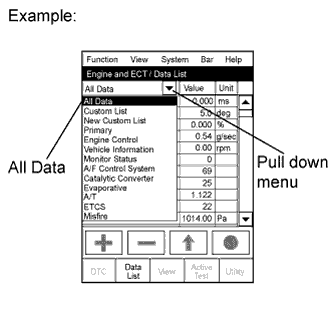 |
Enter the following menus: Powertrain / Engine and ECT / Data List.
Read the Data List on the tester's screen.
| Intelligent Tester Display | Measurement Item/Range (Display) | Normal Condition*
| Diagnostic Note |
| Injector | Injection period of the No. 1 cylinder/ Min.: 0 ms, Max.: 32.64 ms | Idling: 1 to 3 ms | - |
| IGN Advance | Ignition timing advance for No. 1 cylinder/ Min.: -64°, Max.: 63.5° | Idling: BTDC 0 to 20° | - |
| Calculate Load | ECM calculated load/ Min.: 0%, Max.: 100% |
| - |
| Vehicle Load | Vehicle load/ Min.: 0%, Max.: 100% | Actual vehicle load | - |
| MAF | Air flow rate from MAF meter/ Min.: 0 g/s, Max.: 665.35 g/s |
| If the value is approximately 0.0 g/s:
|
| Engine Speed | Engine speed/ Min.: 0 rpm, Max.: 16,383.75 rpm | Idling: 600 to 700 rpm | - |
| Vehicle Speed | Vehicle speed/ Min.: 0 km/h, Max.: 255 km/h | Actual vehicle speed | Speed indicated on speedometer |
| Coolant Temp | Engine coolant temperature/ Min.: -40°C (-40°F) Max.: 215°C (419°F) | After warming up the engine: 80 to 95°C (176 to 203°F) |
|
| Intake Air | Intake air temperature/ Min.: -40°C (-40°F) Max.: 215°C (419°F) | Equivalent to ambient air temperature |
|
| Air-Fuel Ratio | Air-fuel ratio/ Min.: 0, Max.: 1.999 | Idling: 0.8 to 1.2 | 80 to 90°C (176 to of 194°F) of coolant temperature |
| Purge Density Lean Value | Learning value of purge density/ Min.: -50%, Max.: 350% | Idling: -25 to 1% | Service data |
| Purge Flow | Purge flow/ Min.: 0%, Max.: 102.4% | Idling: 0 to 6% | - |
| Knock Correct Learn Value | Correction learning value of knocking/ Min.: -64° CA, Max.: 1,984° CA | 0 to 18.5°CA Driving: 70 km/h (44 mph) | Service data |
| Knock Feedback Value | Feedback value of knocking/ Min.: -64°CA, Max.: 1,984°CA | -10 to 0°CA Driving: 70 km/h (44 mph) | Service data |
| Accelerator Position No. 1 | Absolute accelerator pedal position No. 1/ Min.: 0%, Max.: 100% | 10 to 22%: accelerator pedal is released 54 to 86%: accelerator pedal is fully depressed | - |
| Accelerator Position No. 2 | Absolute accelerator pedal position No. 2/ Min.: 0%, Max.: 100% | 12 to 42%: accelerator pedal is released 66 to 98%: accelerator pedal is fully depressed | - |
| Accelerator Position No. 1 | Accelerator pedal position sensor No. 1 output voltage/ Min.: 0 V, Max.: 4.98 V | - | ETCS freeze data |
| Accelerator Position No. 2 | Accelerator pedal position sensor No. 1 output voltage/ Min.: 0 V, Max.: 4.98 V | - | ETCS freeze data |
| Accelerator Position No. 1 | Accelerator pedal position sensor No. 1 output voltage/ Min.: 0 V, Max.: 5 V |
| - |
| Accelerator Position No. 2 | Accelerator pedal position sensor No. 2 output voltage/ Min.: 0 V, Max.: 5 V |
| - |
| Accelerator Idle Position | Whether or not accelerator pedal position sensor is detecting idle/ ON or OFF | Idling: ON (inspection mode) | - |
| Throttle Fully Close Learn | Throttle fully closed (learned value)/ Min.: 0 V, Max.: 5 V | 0.4 to 0.8 V | - |
| Accel Fully Close #1 (AD) | Accelerator fully closed value No. 1 (AD)/ Min.: 0 V, Max.: 4.9804 V | - | ETCS service data |
| Accel Fully Close Learn #1 | Accelerator fully closed learning value No. 1 / Min.: 0°, Max.: 124.512° | - | ETCS service data |
| Accel Fully Close Learn #2 | Accelerator fully closed learning value No. 2 / Min.: 0°, Max.: 124.512° | - | ETCS service data |
| Fail Safe Drive | Whether or not fail-safe function is executed/ ON or OFF | ETCS has failed: ON | - |
| Fail Safe Drive (Main CPU) | Whether or not fail-safe function is executed/ ON or OFF | ETCS has failed: ON | - |
| ST1 | Brake pedal/ ON or OFF | Released: ON Depressed: OFF | - |
| System Guard | System guard/ ON or OFF | - | ETCS service data |
| Open Side Malfunction | Open side malfunction/ ON or OFF | - | ETCS service data |
| Throttle Position | Absolute throttle position sensor/ Min.: 0%, Max.: 100% |
| Read the value with intrusive operation (active test) |
| Throttle Idle Position | Whether or not throttle position sensor is detecting idle/ ON or OFF | Idling: ON (inspection mode) | - |
| Throttle Require Position | Throttle requirement position/ Min.: 0 V, Max.: 5 V | Idling: 0.4 to 4.5 V (Inspection mode) | - |
| Throttle Sensor Position | Throttle sensor positioning/ Min.: 0%, Max.: 100% | Idling 0 to 10% (Inspection mode) | Calculated value based on VTA1 |
| Throttle Sensor Position #2 | Throttle sensor positioning #2/ Min.: 0%, Max.: 100% | - | Calculated value based on VTA2 |
| Throttle Position No. 1 | Throttle position sensor No. 1 output voltage/ Min.: 0 V, Max.: 4.98 V | - | ETCS service data |
| Throttle Position No. 2 | Throttle position sensor No. 2 output voltage/ Min.: 0 V, Max.: 4.98 V | - | ETCS service data |
| Throttle Position No. 1 | Throttle position No. 1/ Min.: 0 V, Max.: 5 V |
| - |
| Throttle Position No. 2 | Throttle position No. 2/ Min.: 0 V, Max.: 5 V |
| Read the value with intrusive operation (Active Test) |
| Throttle Position Command | Throttle position command value/ Min.: 0 V, Max.: 4.9804 V | 0.5 to 4.8 V | ETCS service data |
| Throttle Sens Open Pos #1 | Throttle sensor opener position No. 1/ Min.: 0, Max.: 4.9804 V | 0.6 to 0.9 V | ETCS service data |
| Throttle Sens Open Pos #2 | Throttle sensor opener position No. 2/ Min.: 0, Max.: 4.9804 V | 2.2 to 2.6 V | ETCS service data |
| Throttle Sens Open #1 (AD) | Throttle sensor opener position No.1 (AD)/ Min.: 0 V, Max.: 4.9804 V | 0.6 to 0.9 V | ETCS service data |
| Throttle Motor | Whether or not throttle motor control is permitted/ ON or OFF | Idling: ON (Inspection mode) | Read the value with the Ignition switch ON (Do not start engine) |
| Throttle Motor Current | Throttle motor current Min.: 0 A, Max.: 80 A | Idling: 0 to 40 A (Inspection mode) | - |
| Throttle Motor | Throttle motor Min.: 0%, Max.: 100% | Idling: 0.5 to 40% (Inspection mode) | - |
| Throttle Motor Current | Throttle motor current/ Min.: 0 A, Max.: 19.92 A | Idling: 0 to 3.0 A | - |
| Throttle Motor Open Duty | Throttle motor opening duty ratio/ Min.: 0%, Max.: 100% | During idling: 0 to 40% | When accelerator pedal is depressed, duty ratio is increased |
| Throttle Motor Close Duty | Throttle motor closed duty ratio/ Min.: 0%, Max.: 100% | During idling: 0 to 40% | When accelerator pedal is released quickly, duty ratio is increased |
| Throttle Motor Duty (Open) | Throttle motor duty ratio (open)/ Min.: 0%, Max.: 100% | - | ETCS service data |
| Throttle Motor Duty (Close) | Throttle motor duty ratio (close)/ Min.: 0%, Max.: 100% | - | ETCS service data |
| O2S B1 S2 | Heated oxygen sensor output voltage for bank 1 sensor 2/ Min.: 0 V, Max.: 1.275 V | Driving 70 km/h (44 mph): 0.1 to 0.9 V | Performing Control the Injection Volume or Control the Injection Volume for A/F Sensor function of Active Test enables technician to check output voltage of sensor |
| AFS B1 S1 | A/F sensor output voltage for bank 1 sensor 1/ Min.: 0 V, Max.: 7.999 V | Idling: 2.8 to 3.8 V | Performing Control the Injection Volume or Control the Injection Volume for A/F Sensor function of Active Test enables technician to check output voltage of sensor |
| Total FT #1 | Total fuel trim of bank 1 Average value for fuel trim system of bank 1/ Min.: -0.5, Max.: 0.496 | Idling: -0.2 to 0.2 | - |
| Short FT #1 | Short-term fuel trim of bank 1/ Min.: -100%, Max.: 99.2% | -20 to 20% | Short-term fuel compensation used to maintain air-fuel ratio at stoichiometric air-fuel ratio |
| Long FT #1 | Long-term fuel term of bank 1/ Min.: -100%, Max.: 99.2% | -20 to 20% | Overall fuel compensation carried out in long-term to compensate continual deviation of short-term fuel trim from central value |
| Fuel System Status (Bank 1) | Fuel system status (Bank 1) / OL, CL, OL DRIVE, OL FAULT or CL FAULT | Idling after warming up: CL (Inspection mode) |
|
| O2FT B1 S2 | Short-term fuel trim associated with bank 1 sensor 2/ Min.: -100%, Max.: 99.2% | -20 to 20% | Same as Short FT #1 |
| AF FT B1 S1 | Short-term fuel trim associated with bank 1 sensor 1/ Min.: 0%, Max.: 1.999% |
| - |
| Initial Engine Coolant Temp | Initial engine coolant temperature/ Min.: -40°C, Max.: 120°C | Close to ambient temperature | Service data |
| Initial Intake Air Temp | Initial intake air temperature/ Min.: -40°C, Max.: 120°C | Close to ambient temperature | Service data |
| Injection Volume (Cylinder 1) | Injection volume (cylinder 1)/ Min.: 0 ml, Max.: 2.048 ml | 0 to 0.5 ml | Quantity of fuel injection volume for 10 times |
| Starter Signal | Starter signal: ON or OFF | ON: Cranking | - |
| Power Steering Switch | Power steering signal/ ON or OFF | ON: Power steering operation | - |
| Power Steering Switch | Power steering signal/ ON or OFF | ON: When steering wheel first turned after ignition switch turned to ON | This signal status usually ON until ignition switch turned to OFF |
| Closed Throttle Position SW | Closed throttle position switch (idle switch)/ ON or OFF | ON: throttle valve is closed | - |
| A/C Signal | A/C Signal/ ON or OFF | ON: A/C switch is turned ON | - |
| Neutral Position SW Signal | Park/Neutral position switch signal/ ON or OFF | P or N position: ON | - |
| Electrical Load Signal | Electrical load signal: ON or OFF | ON: headlights or defogger is turned ON | - |
| Stop Light Switch | Stop light switch: ON or OFF | ON: brake pedal is depressed | - |
| ETCS Actuator Power | Whether or not electric throttle control system power is inputted/ ON or OFF | Idling: ON (inspection mode) | - |
| +BM Voltage | +BM voltage/ Min.: 0 V, Max.: 19.922 V | Idling: 10 to 15 V | ETCS service data |
| Battery Voltage | Battery voltage/ Min.: 0 V, Max.: 65.535 V | Idling: 9 to 14 V (Inspection mode) | - |
| Actuator Power Supply | Actuator power supply/ ON or OFF | Idling ON (Inspection mode) | ETCS service data |
| Atmosphere Pressure | Atmosphere pressure/ Min.: 0 kPa, Max.: 150 kPa | - | - |
| Secondary Air Control VSV | Secondary air injection system status/ ON or OFF | ON: Secondary air injection system operation | - |
| ACT VSV | A/C cut status for Active Test/ ON or OFF | - | Active Test support data |
| EVAP Purge VSV | VSV status for EVAP control ON or OFF | - | Active Test support data |
| Fuel Pump/Speed Status | Fuel pump/speed status/ ON or OFF | Idling: ON (Inspection mode) | - |
| VVT Control Status | VVT control status/ ON or OFF | - | Support for VVT Active Test |
| TC and TE1 | TC and TE1 terminal of DLC3/ ON or OFF | - | - |
| AI Operation Prohibit | Secondary air injection system operation prohibit/ OK or NG | - | - |
| VVT Aim Angle (Bank 1) | VVT aim angle (bank 1)/ Min.: 0%, Max.: 100% | Idling: 0% | VVT duty signal value during forcible operation |
| VVT Change Angle (Bank 1) | VVT change angle/ Min.: 0°FR, Max.: 60°FR | Idling: 0 to 5°FR | Displacement angle during forcible operation |
| VVT OCV Duty (Bank 1) | VVT OCV operation duty/ Min.: 0%, Max.: 100% | Idling: 0% | Requested duty valve for forcible operation |
| Idle Fuel Cut | Fuel cut idle/ ON or OFF | Fuel cut operation: ON | FC IDL = "ON" when throttle valve fully closed and engine speed is over 2,800 rpm |
| FC TAU | Fuel cut TAU: Fuel cut during very light load/ ON or OFF | Fuel cut operating: ON | The fuel cut is being performed under very light load to prevent the engine combustion from becoming incomplete |
| Ignition | Ignition counter/ Min.: 0, Max.: 800 | 0 to 800 | - |
| Cylinder #1, #2, #3, #4 Misfire Rate | Misfire ratio of cylinder 1 to 4/ Min.: 0%, Max.: 50% | 0% | This item is displayed only when idling |
| All Cylinders Misfire Rate | All cylinders misfire rate/ Min.: 0, Max.: 255 | 0 to 35 | - |
| Misfire RPM | Engine rpm for first misfire range/ Min.: 0 rpm, Max.: 6,375 rpm | Misfire 0: 0 rpm | - |
| Misfire Lode | Engine lode for first misfire range/ Min.: 0 g/rev., Max.: 3.98 g/rev. | Misfire 0: 0 g/rev. | - |
| Misfire Margin | Misfire monitoring/ Min.: -100%, Max.: 99.22% | -100 to 99.22% | Misfire detecting margin |
| #Codes | #Codes/ Min.: 0, Max.: 255 | - | Number of detected DTC |
| Check Mode | Check mode/ ON or OFF | Check mode ON: ON | Click here
|
| SPD Test | Check mode result for vehicle speed sensor/ 0: COMPL, 1: INCOMPL | - | - |
| Misfire Test | Check mode result for misfire monitor/ 0: COMPL, 1: INCOMPL | - | - |
| OXS1 Test | Check mode result for HO2 sensor/ 0: COMPL, 1: INCOMPL | - | - |
| A/F Test Results (Bank 1) | Check mode result for air-fuel ratio sensor/ 0: COMPL, 1: INCOMPL | - | - |
| MIL | CHK ENG status/ ON or OFF | CHK ENG ON: ON | - |
| MIL ON Run Distance | Distance traveled while MIL is activated/ Min.: 0 km, Max.: 65,535 km | Distance after DTC is detected | - |
| Running Time from MIL ON | Running time from MIL ON/ Min.: 0 minutes, Max.: 65,535 minutes | Equivalent to running time after MIL is turned on | - |
| Engine Run Time | Engine run time/ Min.: 0 seconds, Max.: 65,535 seconds | Time after engine start | Service data |
| Time after DTC Cleared | Time after DTC cleared/ Min.: 0 minutes, Max.: 65,535 minutes | Equivalent to time after DTC was erased | - |
| Distance from DTC Cleared | Distance from DTC cleared/ Min.: 0 km, Max.: 65,535 km | Equivalent to drive distance after DTCs were erased | - |
| Warm-up Cycle Cleared DTC | Warm-up cycle after DTC cleared/ Min.: 0, Max.: 255 | - | Number of warm-up cycles after DTC is cleared |
| Model Code | Model code | - | Identifying the model code: TGN### |
| Engine Type | Engine type | - | Identifying the engine type: 2TR-FE |
| Cylinder Number | Cylinder number/ Min.: 0, Max.: 255 | - | Identifying the cylinder number: 4 |
| Transmission Type | Transmission type | - | Identifying the transmission type: MT |
| Destination | Destination | - | Identifying the destination: W |
| Model Year | Model year/ Min.: 1900, Max.: 2155 | - | Identifying the model year: 200# |
| System Identification | System identification | - | Identifying the engine system: GASLIN (gasoline engine) |
| Number of Emission DTC | Number of Emission DTCs | - | - |
| Complete parts Monitor | Complete parts monitor/ 0: NOT AVL / 1: AVAIL | - | - |
| Fuel System Monitor | Fuel system monitor/ 0: NOT AVL / 1: AVAIL | - | - |
| Misfire Monitor | Misfire monitor/ 0: NOT AVL / 1: AVAIL | - | - |
| O2S (A/FS) Monitor | O2S (A/FS) monitor/ 0: COMPL / 1: INCOMPL | - | - |
| O2S (A/FS) Monitor | O2S (A/FS) monitor/ 0: COMPL / 1: INCOMPL | - | - |
| Catalyst Monitor | Catalyst monitor/ 0: COMPL / 1: INCOMPL | - | - |
| Catalyst Monitor | Catalyst monitor/ 0: COMPL / 1: INCOMPL | - | - |
| PERFORM ACTIVE TEST |
Warm up the engine.
Turn the ignition switch OFF.
Connect the intelligent tester to the DLC3.
Turn the Ignition switch ON.
Turn the intelligent tester ON.
Enter the following menus: Powertrain / Engine and ECT / Active Test.
According to the display on the tester, perform the Active Test.
| Intelligent Tester Display | Test Details | Control Range | Diagnostic Note |
| Control the Injection Volume | Control injection volume (Engine speed: 3,000 rpm or less) | Min.: -12.5%, Max.: 24.8% |
|
| Control the Injection Volume for A/F Sensor | Change injection volume | Decreases by 12.5% or increases by 24.8% | Following A/F Control procedure enables technician to check and graph output voltages of both A/F sensor and heated oxygen sensor To display graph indication, select following menu items: View / Line graph 1 or Line graph 2 |
| Control the A/C Cut Signal | Control A/C cut signal | ON or OFF | - |
| Activate the VSV for EVAP Control | Activate VSV for EVAP control | ON or OFF | - |
| Control the Fuel Pump / Speed | Control fuel pump | ON or OFF | Engine is stopped |
| Activate the VVT System (Bank 1) | Activate VVT system (Bank 1) | ON or OFF |
|
| Connect the TC and TE1 | Connect TC and TE1 | ON or OFF | - |
| Control the Idle Fuel Cut Prohibit | Control idle fuel cut prohibition | ON or OFF | During idling |
| Control the ETCS Open/Close Slow Speed | Control the ETCS opening/closing slow speed | Open or Close | Test possible when following conditions met:
|
| Control the ETCS Open/Close Fast Speed | Control the ETCS opening/closing fast speed | Open or Close | Test possible when following conditions met:
|
| Control the Cylinder #1 Fuel Cut | Control the cylinder #1 fuel cut | ON or OFF | Cylinder No. 1 fuel cut for power balance
|
| Control the Cylinder #2 Fuel Cut | Control the cylinder #2 fuel cut | ON or OFF | Cylinder No. 2 fuel cut for power balance
|
| Control the Cylinder #3 Fuel Cut | Control the cylinder #3 fuel cut | ON or OFF | Cylinder No. 3 fuel cut for power balance
|
| Control the Cylinder #4 Fuel Cut | Control the cylinder #4 fuel cut | ON or OFF | Cylinder No. 4 fuel cut for power balance
|
| Control the VVT linear (bank 1) | Control the VVT (bank 1) | Min.: -128%, Max.: 127% | - |
| Activate the VSV for Secondary Air Control | Activate the secondary air VSV | ON or OFF | This test activates VSV only 5 seconds. After finishing this test, vehicle does not permit activating VSV again within 30 seconds |
