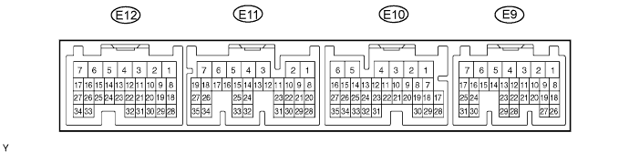
Symbols (Terminal No.)
| Wiring Color
| Terminal Description
| Condition
| Specified Condition
|
BATT (E9-3) - E1 (E12-3)
| L - BR
| Battery (for measuring battery voltage and for ECM memory
| Always
| 9 to 14 V
|
+BM (E9-7) - E1 (E12-3)
| R-W - BR
| Power source of throttle motor
| Always
| 9 to 14 V
|
IGSW (E9-9) - E1 (E12-3)
| B-O - BR
| Ignition switch
| Ignition switch ON
| 9 to 14 V
|
+B (E9-1) - E1 (E12-3)
| B - BR
| Power source of ECM
| Ignition switch ON
| 9 to 14 V
|
MREL (E9-8) - E1 (E12-3)
| W-G - BR
| EFI relay
| Ignition switch ON
| 9 to 14 V
|
VC (E12-18) - E2 (E12-28)
| LG-B - BR
| Power source of sensor (specific voltage)
| Ignition switch ON
| 4.5 to 5.5 V
|
VTA1 (E12-20) - E2 (E12-28)
| B-R - BR
| Throttle position sensor (for engine control
| Ignition switch ON, accelerator pedal fully released
| 0.5 to 1.1 V
|
VTA1 (E12-20) - E2 (E12-28)
| B-R - BR
| Throttle position sensor (for engine control)
| Ignition switch ON, accelerator pedal fully depressed
| 3.2 to 4.8
|
VTA2 (E12-19) - E2 (E12-28)
| LG - BR
| Throttle position sensor (for sensor malfunction detection)
| Ignition switch ON, accelerator pedal fully released
| 2.1 to 3.1
|
VTA2 (E12-19) - E2 (E12-28)
| LG - BR
| Throttle position sensor (for sensor malfunction detection)
| Ignition switch ON, accelerator pedal fully depressed
| 4.5 to 5.5
|
VPA (E9-18) - EPA (E9- 20)
| W-L - BR-W
| Accelerator pedal position sensor (for engine control)
| Ignition switch ON, accelerator pedal fully released
| 0.5 to 1.1 V
|
VPA (E9-18) - EPA (E9- 20)
| W-L - BR-W
| Accelerator pedal position sensor (for engine control)
| Ignition switch ON, accelerator pedal fully depressed
| 2.5 to 4.6 V
|
VPA2 (E9-19) - EPA2 (E9-21)
| GR-G - BR-Y
| Accelerator pedal position sensor (for sensor malfunction detection)
| Ignition switch ON, accelerator pedal fully released
| 1.5 to 2.9 V
|
VPA2 (E9-19) - EPA2 (E9-21)
| GR-G - BR-Y
| Accelerator pedal position sensor (for sensor malfunction detection)
| Ignition switch ON, accelerator pedal fully depressed
| 3.5 to 5.5 V
|
VCPA (E9-26) - EPA (E9-20)
| LG-R - BR-W
| Power source of accelerator pedal position sensor (for VPA)
| Ignition switch ON
| 4.5 to 5.5 V
|
VCP2 (E9-27) - EPA2 (E9-21)
| BR-R - BR-Y
| Power source of accelerator pedal position sensor (for VPA2)
| Ignition switch ON
| 4.5 to 5.5 V
|
VG (E11-28) - E2G (E11-30)
| L-W - L-R
| MAF meter
| Idling, shift position on P or N, A/C switch off
| 0.5 to 3.0 V
|
THA (E11-29) - E2 (E12-28)
| L-B - BR
| IAT sensor
| Idling, intake air temperature 20°C (68°F)
| 0.5 to 3.4 V
|
THW (E12-32) - E2 (E12-28)
| B - BR
| ECT sensor
| Idling, engine coolant temperature 80°C (176°F)
| 0.2 to 1.0 V
|
#10 (E11-6) - E01 (E12-7)
#20 (E11-5) - E01 (E12-7)
#30 (E11-2) - E01 (E12-7)
#40 (E11-1) - E01 (E12-7)
| L - W-B
G - W-B
R - W-B
W - W-B
| Injector
| Ignition switch ON
| 9 to 14 V
|
#10 (E11-6) - E01 (E12-7)
#20 (E11-5) - E01 (E12-7)
#30 (E11-2) - E01 (E12-7)
#40 (E11-1) - E01 (E12-7)
| L - W-B
G - W-B
R - W-B
W - W-B
| Injector
| Idling
| Pulse generation (see waveform 6)
|
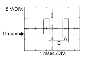
IGT1 (E12-17) - E1 (E12-3)
IGT2 (E12-16) - E1 (E12-3)
IGT3 (E12-15) - E1 (E12-3)
IGT4 (E12-14) - E1 (E12-3)
| R - BR
R-L - BR
G-B - BR
G - BR
| Ignition coil with igniter ignition signal
| Idling
| Pulse generation (see waveform 5)
|
IGF (E12-23) - E1 (E12-3)
| G-R - BR
| Ignition coil with igniter (ignition confirmation signal
| Ignition switch ON
| 4.5 to 5.5 V
|
IGF (E12-23) - E1 (E12-3)
| G-R - BR
| Ignition coil with igniter (ignition confirmation signal
| Idling
| Pulse generation (see waveform 5)
|
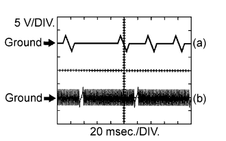
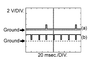
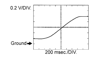
G2+ (E12-26) - NE- (E12-34)
| R - G
| Camshaft position sensor
| Idling
| Pulse generation (see waveform 3)
|
NE+ (E12-27) - NE- (E12-34)
| L - G
| Crankshaft position sensor
| Idling
| Pulse generation (see waveform 3)
|
FC (E9-25) - E01 (E12-7)
| LG-B - W-B
| Fuel pump control
| Ignition switch ON
| 9 to 14 V
|
A1A+ (E12-21) - E1 (E12-3)
| B - BR
| A/F sensor
| Always (Ignition switch ON)
| Fixed at 3.3 V *1
|
A1A- (E12-31) - E1 (E12-3)
| W - BR
| A/F sensor
| Always (Ignition switch ON)
| Fixed at 3.3 V *1
|
HA1A (E12-1) - E04 (E11-7)
| Y - W-B
| A/F sensor heater
| Idling
| Below 3.0 V
|
HA1A (E12-1) - E04 (E11-7)
| Y - W-B
| A/F sensor heater
| Ignition switch ON
| 9 to 14 V
|
OX1B (E12-25)*3 - E2 (E12-28)
| B - BR
| Heated oxygen sensor
| Maintain engine speed at 2,500 rpm for 2 minutes after warming up sensor
| Pulse generation (see waveform 10)
|
HT1B (E12-2) - E03 (E11-4)
| L-Y - W-B
| Heated oxygen sensor heater
| Idling
| Below 3.0 V
|
HT1B (E12-2) - E03 (E11-4)
| L-Y - W-B
| Heated oxygen sensor heater
| Ignition switch ON
| 9 to 14 V
|
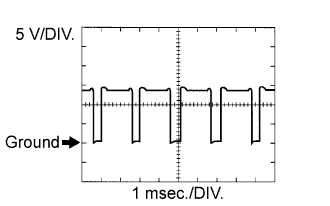
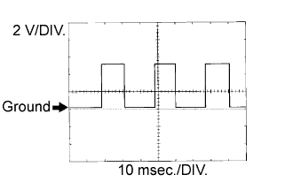
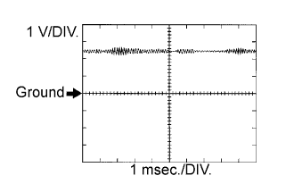
M+ (E12-5) - ME01 (E11-3)
| B - W-B
| Throttle actuator
| Idling
| Pulse generation (see waveform 1)
|
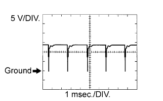
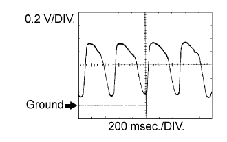
M- (E12-4) - ME01 (E11-3)
| W - W-B
| Throttle actuator
| Idling
| Pulse generation (see waveform 2)
|
KNK1 (E12-29) - EKNK (E12-30)
| B - W
| Knock sensor
| Maintain engine speed at 4,000 rpm after warming up engine
| Pulse generation (see waveform 8)
|
OC+ (E12-13) - OC1- (E12-12)
| P-L - Y
| Camshaft timing oil control valve
| Ignition switch ON
| Pulse generation (see waveform 7)
|
PRG (E11-23) - E01 (E12-7)
| L - W-B
| VSV for EVAP
| Ignition switch ON
| 9 to 14 V
|
PRG (E11-23) - E01 (E12-7)
| L - W-B
| VSV for EVAP
| Idling
| Pulse generation (see waveform 11)
|
STA (E9-12) - E1 (E12-3)
| L-Y - BR
| Starter signal
| Shift position on P or N, ignition switch START
| 6.0 V or more
|
ALT (E12-10) - E1 (E12-3)
| G - BR
| Generator
| Ignition switch ON
| 9 to 14 V
|
STP (E10-4) - E1 (12-3)
| G-W - BR
| Stop light switch
| Brake pedal depressed
| 9 to 14 V
|
STP (E10-4) - E1 (12-3)
| G-W - BR
| Stop light switch
| Brake pedal released
| Below 1.5 V
|
ST1- (E9-16) - E1 (E12-3)
| R-L - BR
| Stop light switch
| Ignition switch ON, brake pedal depressed
| Below 1.5 V
|
ST1- (E9-16) - E1 (E12-3)
| R-L - BR
| Stop light switch
| Ignition switch ON, brake pedal released
| 7.5 to 14 V
|
W (E10-30) - E1 (E12-3)
| R-B - BR
| MIL
| Idling
| 9 to 14 V
|
W (E10-30) - E1 (E12-3)
| R-B - BR
| MIL
| Ignition switch ON
| Below 3.0 V
|
ELS1 (E9-15) - E1 (E12-3)
| G - BR
| Electric load
| Taillight switch on
| 7.5 to 14 V
|
ELS1 (E9-15) - E1 (E12-3)
| G - BR
| Electric load
| Taillight switch off
| 0 to 1.5 V
|
ELS3 (E10-3) - E1 (E12-3)
| B - BR
| Defogger
| Defogger switch ON
| 7.5 to 14 V
|
ELS3 (E10-3) - E1 (E12-3)
| B - BR
| Defogger
| Defogger switch OFF
| 0 to 1.5 V
|
TACH (E10-1) - E1 (E12-3)
| B-W - BR
| Engine speed
| Idling
| Pulse generation
|
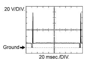
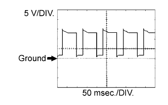
SPD (E10-8) - E1 (E12-3)
| V-R - BR
| Speed signal from combination meter
| Ignition switch ON, slowly turn wheel
| Pulse generation (see waveform 4)
|
TC (E10-17) - E1 (E12-3)
| P-B - BR
| Terminal TC of DLC3
| Ignition switch ON
| 9 to 14 V
|
SIL (E10-13) - E1 (E12-3)
| R-Y - BR
| Terminal SIL of DLC3
| Connect intelligent tester to DLC3
| Pulse generation
|
PSW (E11-32) - E1 (E12-3)
| G-Y - BR
| Power steering oil pressure switch
| While turning steering wheel
| Below 1.5 V
|
F/PS (E10-32) - E1 (E12-3)
| B - BR*2
| Center airbag sensor assembly center
| Ignition switch ON
| Pulse generation
|
AIRP (E12-11) - E1 (E12-3)
| W-L - BR
| Air switching valve for secondary air injection system
| Idling
| 9 to 14 V
|
AIRV (E12-24) - E1 (E12-3)
| V - BR
| Air pump control
| Idling
| 9 to 14 V
|
AIDI (E11-20) - E1 (E12-3)
| G-W - BR
| Diagnostic information signal for air injection system
| Air injection system operates
| Pulse generation (see waveform 12)
|
VAF (E12-25)*4 - E1 (E12-3)
| G-B - BR
| Variable resistor
| Ignition switch ON
| 0 to 5.0 V
|