WIRELESS DOOR LOCK CONTROL SYSTEM > Only Wireless Control Function is Inoperative |
| 1.CHECK WIRELESS DOOR LOCK CONTROL FUNCTIONS |
|
| ||||
| NG | |
| 2.CHECK THAT TRANSMITTER LED ILLUMINATES |
Check that the transmitter's LED illuminates 3 times when the switch is pressed 3 times.
|
| ||||
| OK | |
| 3.CHECK WIRELESS DOOR LOCK CONTROL FUNCTION (STANDARD OPERATION FUNCTION) |
Hold the transmitter approximately 1 m (3.28 ft.) from the driver side door outside handle. The transmitter must be parallel to the ground and perpendicular to the side of the vehicle.
Press and hold either the LOCK or UNLOCK transmitter switch for 1 second, and check that the doors lock or unlock, respectively.
|
| ||||
| OK | ||
| ||
| 4.REPLACE TRANSMITTER BATTERY |
After replacing the transmitter battery (Click here), check that the doors can be locked and unlocked using the transmitter switches.
|
| ||||
| OK | ||
| ||
| 5.CHECK NO.1 ROOM LIGHT ASSEMBLY |
Check that the No. 1 room light assembly illumination operates normally.
|
| ||||
| OK | |
| 6.SWITCH TO SELF-DIAGNOSTIC MODE |
Switch to self-diagnostic mode by operating the ignition key cylinder.
Make sure the vehicle is in its initial condition (Click here). Then insert the key into the ignition key cylinder and remove it.
Within 5 seconds of removing the key, insert the key into the ignition key cylinder (ignition switch OFF). Then turn the ignition switch ON and OFF.
Within 30 seconds of turning the ignition switch OFF, perform the following 9 times: turn the ignition switch ON and OFF.
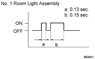 |
Check that the system has switched to self-diagnostic mode by checking the No. 1 room light assembly flash pattern.
|
| ||||
| OK | |
| 7.CHECK BY SELF-DIAGNOSTIC MODE |
Inspect the diagnosis outputs when the door control transmitter switch is held down. The diagnosis outputs can be checked by the flash patterns of the No. 1 room light assembly.
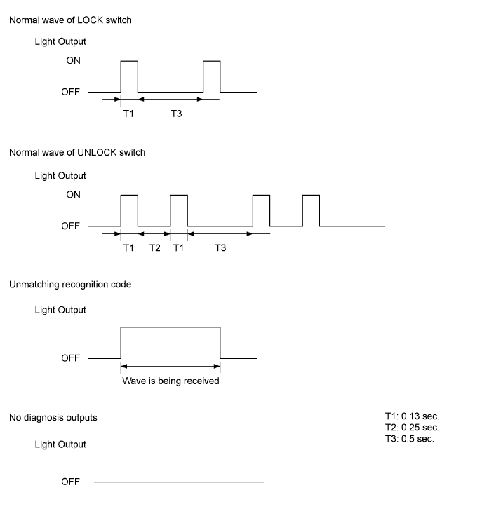
| Result | Proceed to |
| Unmatching recognition code is output | A |
| Normal waves (light flash patterns) for LOCK and UNLOCK switches are output | B |
| No diagnosis outputs are present | C |
|
| ||||
|
| ||||
| A | |
| 8.REGISTER RECOGNITION CODE |
Check that the system can be switched to rewrite mode or add mode, and that a recognition code can be registered.
|
| ||||
| OK | ||
| ||
| 9.CHECK RESPONSE OF DOOR CONTROL RECEIVER |
When a new or normally functioning door lock control transmitter switch for the same type vehicle is held down, check that an unmatching recognition code is output.
|
| ||||
| NG | |
| 10.REPLACE DOOR CONTROL RECEIVER |
After replacing the door control receiver (Click here), check that the doors can be locked and unlocked by using the transmitter LOCK / UNLOCK switch.
|
| ||||
| OK | ||
| ||
| 11.CONFIRM INPUT METHOD OF SELF-DIAGNOSTIC MODE |
| Result | Proceed to |
| Method for changing system to self-diagnostic mode works | A |
| Method for changing system to self-diagnostic mode does not work | B |
|
| ||||
| A | |
| 12.INSPECT UNLOCK WARNING SWITCH ASSEMBLY |
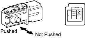 |
Remove the switch.
Measure the voltage and resistance of the switch.
| Tester Connection | Switch Condition | Specified Condition |
| 1 - 2 | Not pushed | 10 kΩ or higher |
| Pushed | Below 1 Ω |
|
| ||||
| OK | |
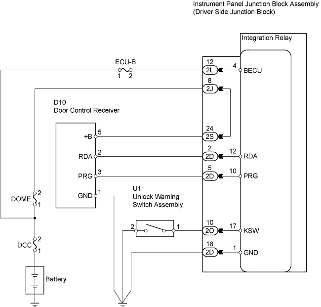
| 13.CHECK WIRE HARNESS (DOOR CONTROL RECEIVER - INSTRUMENT PANEL JUNCTION BLOCK) |
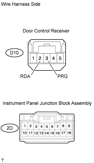 |
Disconnect the D10 receiver connector.
Disconnect the 2D junction block connector.
Measure the resistance of the wire harness side connectors.
| Tester Connection | Specified Condition |
| D10-3 (PRG) - 2D-2 | Below 1 Ω |
| D10-2 (RDA) - 2D-5 | Below 1 Ω |
|
| ||||
| OK | |
| 14.CHECK DOOR CONTROL RECEIVER (OUTPUT) |
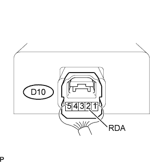 |
Reconnect the D10 receiver connector.
Measure the resistance of the connector.
| Tester Connection | Condition | Specified Condition |
| D10-2 (RDA) - Body ground | Transmitter switch ON → OFF (No key in ignition key cylinder, all doors closed) | Below 1 V → 6 to 7 V → Below 1 V |
|
| ||||
| NG | |
| 15.REPLACE DOOR CONTROL TRANSMITTER MODULE |
Check that the doors can be locked and unlocked by using the transmitter LOCK / UNLOCK switch.
|
| ||||
| OK | ||
| ||
