DTC B2796 No Communication in Immobiliser System |
DTC B2798 Communication Malfunction No. 2 |
| DTC No. | DTC Detection Condition | Trouble Area |
| B2796 | No communication |
|
| B2798 | Communication error | Key |
| 1.READ VALUE OF INTELLIGENT TESTER (ENGINE IMMOBILISER SYSTEM) |
Check the Data List for proper functioning of the engine immobiliser system.
| Item | Measurement Item / Display (Range) | Normal Condition | Diagnostic Note |
| Immobiliser | Immobiliser system status / SET or UNSET | UNSET: Ignition switch ON SET: No key is in ignition key cylinder | - |
|
| ||||
| NG | |
| 2.CHECK WHETHER ENGINE STARTS WITH OTHER KEY |
Check whether the engine starts with the vehicle's other keys.
|
| ||||
| NG | |
| 3.READ VALUE OF INTELLIGENT TESTER (TRANSPONDER KEY COIL) |
Check the Data List for proper functioning of the transponder key coil.
| Item | Measurement Item / Display (Range) | Normal Condition | Diagnostic Note |
| Antenna Coil Status | Transponder key coil condition / NORMAL or FAIL | NORMAL: Transponder key coil is normal FAIL: Transponder key coil is malfunctioning | - |
|
| ||||
| NG | |
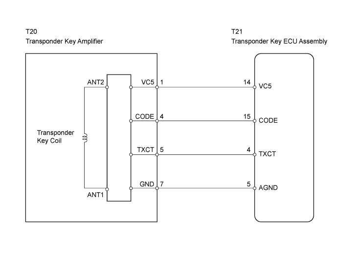
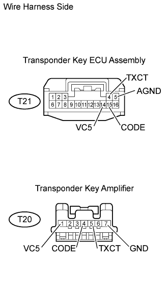
| 4.CHECK WIRE HARNESS (TRANSPONDER KEY ECU ASSEMBLY - TRANSPONDER KEY AMPLIFIER) |
 |
Disconnect the T21 ECU connector.
Disconnect the T20 amplifier connector.
Measure the resistance of the wire harness side connectors.
| Tester Connection | Specified Condition |
| T21-14 (VC5) - T20-1 (VC5) | Below 1 Ω |
| T21-15 (CODE) - T20-4 (CODE) | Below 1 Ω |
| T21-4 (TXCT) - T20-5 (TXCT) | Below 1 Ω |
| T21-5 (AGND) - T20-7 (GND) | Below 1 Ω |
| T21-14 (VC5) or T20-1 (VC5) - Body ground | 10 kΩ or higher |
| T21-15 (CODE) or T20-4 (CODE) - Body ground | 10 kΩ or higher |
| T21-4 (TXCT) or T20-5 (TXCT) - Body ground | 10 kΩ or higher |
| T21-5 (AGND) or T20-7 (GND) - Body ground | 10 kΩ or higher |
|
| ||||
| OK | |
| 5.CHECK OPERATION OF TRANSPONDER KEY AMPLIFIER |
After replacing the transponder key amplifier with a normally functioning amplifier, check that the engine starts.
|
| ||||
| OK | ||
| ||
