DTC B1900/73 Short in Front Pretensioner Squib RH Circuit |
DTC B1901/73 Open in Front Pretensioner Squib RH Circuit |
DTC B1902/73 Short to GND in Front Pretensioner Squib RH Circuit |
DTC B1903/73 Short to B+ in Front Pretensioner Squib RH Circuit |
| DTC No. | DTC Detection Condition | Trouble Area |
| B1900/73 | When one of following conditions is met:
|
|
| B1901/73 | When one of following conditions is met:
|
|
| B1902/73 | When one of following conditions is met:
|
|
| B1903/73 | When one of following conditions is met:
|
|
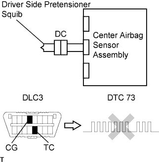
| 1.CHECK FOR DTC |
Proceed to each step according to DTC readings.
If using the intelligent tester (read the 5 digit DTC):
Check for DTCs (Click here).
| Result | Proceed to |
| DTC B1900 is output | A |
| DTC B1901 is output | B |
| DTC B1902 is output | C |
| DTC B1903 is output | D |
If not using the intelligent tester (read the 2 digit DTC):
Check for DTC (Click here).
| Result | Proceed to |
| DTC 73 is output | E |
|
| ||||
|
| ||||
|
| ||||
|
| ||||
| A | |
| 2.CHECK CONNECTOR |
Turn the ignition switch OFF.
Disconnect the cable from the negative (-) battery terminal, and wait for at least 90 seconds.
Check that the floor wire connector (on the front seat outer belt RH side) is not damaged.
|
| ||||
| OK | |
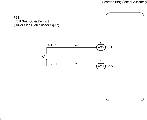
| 3.CHECK FLOOR WIRE (SHORT) |
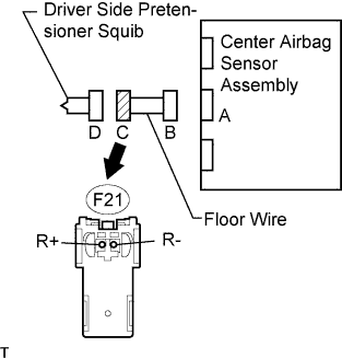 |
Disconnect the connectors from the center airbag sensor and front seat outer belt RH.
Release the activation prevention mechanism built into connector B (Click here).
Measure the resistance of the wire harness side connector.
| Tester Connection | Specified Condition |
| F21-1 (R+) - F21-2 (R-) | 1 MΩ or higher |
|
| ||||
| NG | ||
| ||
| 4.CHECK FLOOR WIRE (OPEN) |
|
Disconnect the connectors from the center airbag sensor and front seat outer belt RH.
Measure the resistance of the wire harness side connector.
| Tester Connection | Specified Condition |
| F21-1 (R+) - F21-2 (R-) | Below 1 Ω |
|
| ||||
| NG | ||
| ||
| 5.CHECK FLOOR WIRE (TO GROUND) |
|
Disconnect the connectors from the center airbag sensor and front seat outer belt RH.
Measure the resistance of the wire harness side connector.
| Tester Connection | Specified Condition |
| F21-1 (R+) - Body ground | 1 MΩ or higher |
| F21-2 (R-) - Body ground | 1 MΩ or higher |
|
| ||||
| NG | ||
| ||
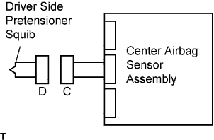
| 6.CHECK FLOOR WIRE (TO B+) |
|
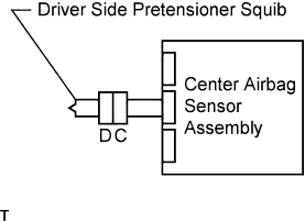
Disconnect the connectors from the center airbag sensor and driver side pretensioner squib.
Connect the cable to the negative (-) battery terminal, and wait for at least 2 seconds.
Turn the ignition switch ON.
Measure the voltage of the wire harness side connector.
| Tester Connection | Specified Condition |
| F21-1 (R+) - Body ground | Below 1 V |
| F21-2 (R-) - Body ground | Below 1 V |
Turn the ignition switch OFF.
Disconnect the cable from the negative (-) battery terminal and wait for at least 90 seconds.
|
| ||||
| NG | ||
| ||
| 7.CHECK CONNECTOR |
Check that the floor wire connector (on the front seat outer belt assembly RH side) is not damaged.
|
| ||||
| OK | |
| 8.CHECK FLOOR WIRE (DRIVER SIDE PRETENSIONER SQUIB CIRCUIT) |
|
Connect the cable to the negative (-) battery terminal, and wait for at least 2 seconds.
Turn the ignition switch ON.
Measure the voltage of the wire harness side connector.
| Tester Connection | Specified Condition |
| F21-1 (R+) - Body ground | Below 1 V |
| F21-2 (R-) - Body ground | Below 1 V |
Turn the ignition switch OFF.
Disconnect the cable from the negative (-) battery terminal, and wait for at least 90 seconds.
Measure the resistance of the wire harness side connector.
| Tester Connection | Specified Condition |
| F21-1 (R+) - F21-2 (R-) | Below 1 Ω |
| F21-1 (R+) - Body ground | 1 MΩ or higher |
| F21-2 (R-) - Body ground | 1 MΩ or higher |
Release the activation prevention mechanism built into connector B (Click here).
Measure the resistance of the wire harness side connector.
| Tester Connection | Specified Condition |
| F21-1 (R+) - F21-2 (R-) | 1 MΩ or higher |
|
| ||||
| OK | |
| 9.REPLACE FRONT SEAT OUTER BELT ASSEMBLY RH (DRIVER SIDE PRETENSIONER SQUIB) |
 |
Replace the front seat outer belt RH (Click here).
Connect the connectors to the center airbag sensor.
Connect the cable to the negative (-) battery terminal, and wait for at least 2 seconds.
Turn the ignition switch ON, and wait for at least 60 seconds.
Clear the DTCs stored in memory (Click here).
Turn the ignition switch OFF.
Turn the ignition switch ON, and wait for at least 60 seconds.
Check for DTCs (Click here).
|
| ||||
| OK | ||
| ||
| 10.CHECK CENTER AIRBAG SENSOR ASSEMBLY |
 |
Connect the connectors to the center airbag sensor.
Connect the cable to the negative (-) battery terminal, and wait for at least 2 seconds.
Turn the ignition switch ON, and wait for at least 60 seconds.
Clear the DTCs stored in memory (Click here).
Turn the ignition switch OFF.
Turn the ignition switch ON, and wait for at least 60 seconds.
Check for DTCs (Click here).
Turn the ignition switch OFF.
Disconnect the cable from the negative (-) battery terminal and wait for at least 90 seconds.
|
| ||||
| NG | ||
| ||
| 11.CHECK CENTER AIRBAG SENSOR ASSEMBLY |
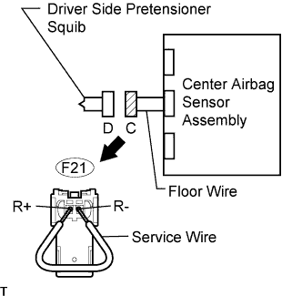 |
Connect the connectors to the center airbag sensor.
Using a service wire, connect terminals F21-1 (R+) and F21-2 (R-) of connector C.
Connect the cable to the negative (-) battery terminal, and wait for at least 2 seconds.
Turn the ignition switch ON, and wait for at least 60 seconds.
Clear the DTCs (Click here).
Turn the ignition switch OFF.
Turn the ignition switch ON, and wait for at least 60 seconds.
Check for DTCs (Click here).
|
| ||||
| OK | |
| 12.CHECK FRONT SEAT OUTER BELT ASSEMBLY RH (DRIVER SIDE PRETENSIONER SQUIB) |
 |
Disconnect the service wire from connector C.
Connect the connector to the front seat outer belt RH.
Connect the cable to the negative (-) battery terminal, and wait for at least 2 seconds.
Turn the ignition switch ON, and wait for at least 60 seconds.
Clear the DTCs (Click here).
Turn the ignition switch OFF.
Turn the ignition switch ON, and wait for at least 60 seconds.
Check for DTCs (Click here).
|
| ||||
| OK | ||
| ||
