AIRBAG SYSTEM > DIAGNOSIS SYSTEM |
| DESCRIPTION |
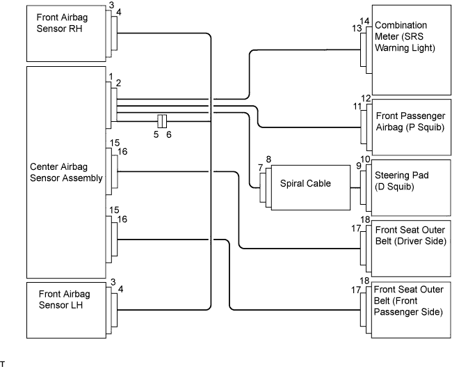
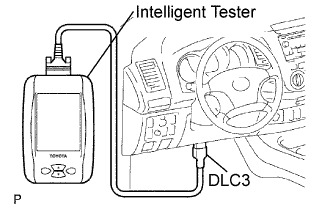
The center airbag sensor controls the functions of the Supplemental Restraint System (SRS) on the vehicle. Data of the SRS can be read in the Data Link Connector 3 (DLC3) of the vehicle. When the system seems to be malfunctioning, use the intelligent tester to check for a malfunction and perform repairs.
| CHECK DLC3 |
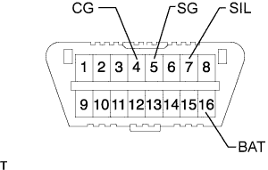  |
The vehicle's ECM uses ISO 14230 (M-OBD) communication protocol. The terminal arrangement of the DLC3 complies with ISO 15031-03 and matches the ISO 14230 format.
| Symbols (Terminal No.) | Terminal Description | Connection | Specified Condition |
| SIL (7) - SG (5) | Bus "+" line | During transmission | Pulse generation |
| CG (4) - Body ground | Chassis ground | Always | Below 1 Ω |
| SG (5) - Body ground | Signal ground | Always | Below 1 Ω |
| BAT (16) - Body ground | Battery positive | Always | Below 1 Ω |
| SYMPTOM SIMULATION |
Vibration method: When vibration seems to be the major cause.
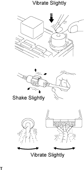 |
Apply slight vibration with a finger to the part of the sensor considered to be the cause of the problem and check whether or not the malfunction occurs.
Slightly shake the connector vertically and horizontally.
Slightly shake the wire harness vertically and horizontally.
| FUNCTION OF SRS WARNING LIGHT |
Primary check
Turn the ignition switch OFF. Wait at least 2 seconds and then turn the ignition switch ON. The SRS warning light illuminates for approximately 6 seconds and the SRS diagnosis is performed.
Constant check
After the primary check, the center airbag sensor constantly monitors the SRS for malfunctions.
Review
When the SRS is normal:
The SRS warning light illuminates only during the primary check period (approximately 6 seconds after the ignition switch is turned ON).
When the SRS is malfunctioning, one of the following may occur:
| SRS WARNING LIGHT CHECK |
 |
Turn the ignition switch ON, and check that the SRS warning light illuminates for approximately 6 seconds (primary check).
Check that the SRS warning light turns off approximately 6 seconds after the ignition switch is turned ON (constant check).
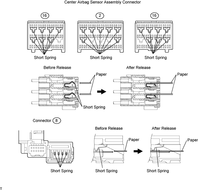
| RELEASE METHOD OF ACTIVATION PREVENTION MECHANISM |
The activation prevention mechanism is built into the connector for the squib circuit of the SRS. As explained in the troubleshooting section, insert a piece of paper that is the same thickness as the male terminal between the terminal and short spring to release the mechanism (refer to the illustrations below).