AIRBAG SYSTEM > PRECAUTION |
| System Name | See procedure |
| Combination Meter System |
Click here
|
| 1.HANDLING PRECAUTIONS FOR AIRBAG SENSOR |
Before replacement of the airbag sensor, wait at least 90 seconds after disconnecting the cable from the negative (-) battery terminal.
When connecting or disconnecting an airbag sensor connector, ensure that all of the sensors are installed in the vehicle.
Do not use the airbag sensors if they have been dropped.
Do not disassemble the airbag sensors.
| 2.INSPECTION PROCEDURE FOR VEHICLE INVOLVED IN ACCIDENT |
When the airbag has not deployed, confirm the DTC by checking the SRS warning light. If there is any malfunction in the SRS, perform troubleshooting.
When any of the airbags have deployed, replace the related airbag sensor and inspect its normal operation.
| 3.SRS CONNECTORS |
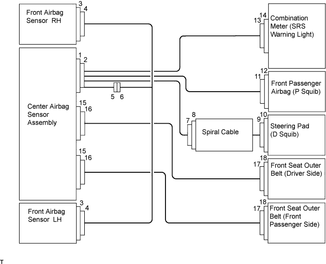
| Connector Type | Application |
| Terminal Twin-lock Mechanism | Connectors 2, 4, 5, 6, 7, 16 |
| Activation Prevention Mechanism | Connectors 2, 8, 10, 12, 16 |
| Half Connection Prevention Mechanism | Connectors 4, 6, 7 |
| Connector Lock Mechanism | Connectors 9, 11, 17 |
All connectors in the SRS are yellow (to distinguish them from other connectors). Some connectors have special functions and are specially designed for the SRS. These connectors use durable gold-plated terminals, and are located as shown on the above page to ensure high reliability.
 |
Terminal twin-lock mechanism:
Activation prevention mechanism:

Half connection prevention mechanism:
Connector lock mechanism:
| 4.DEPLOYMENT CONDITION |
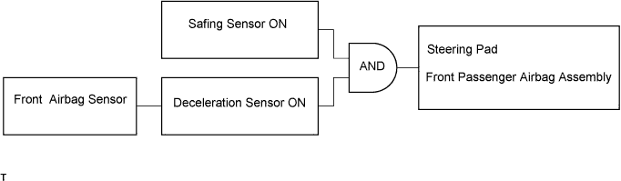
When the vehicle is in a collision and the shock is greater than the specified value, the SRS is activated automatically. The safing sensor and deceleration sensor are built into the center airbag sensor. The safing sensor is designed to be turned on at a smaller deceleration rate than the deceleration sensor. The deceleration sensor determines whether or not SRS deployment is necessary based on signals from the front airbag sensor. Current flows to the squibs to deploy the SRS when the conditions shown in the illustration below are met.
| 5.DISCONNECTION OF CONNECTOR FOR STEERING PAD, FRONT PASSENGER AIRBAG ASSEMBLY, FRONT SEAT OUTER BELT (DRIVER SIDE AND FRONT PASSENGER SIDE) |
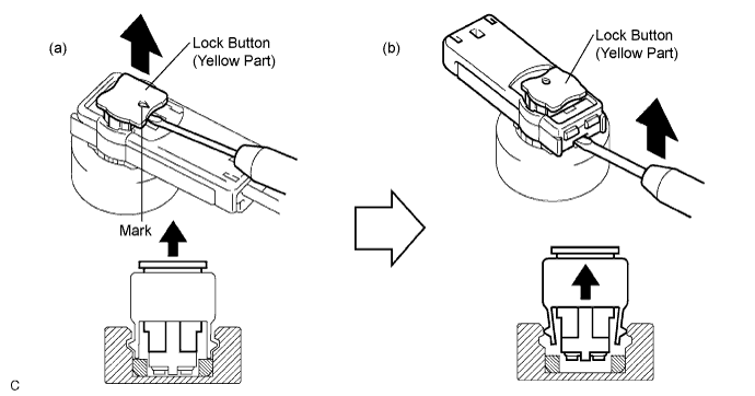
Release the lock button (yellow part) of the connector using a screwdriver.
Insert the screwdriver tip between the connector and base, and then raise the connector.
| 6.CONNECTION OF CONNECTOR FOR STEERING PAD, FRONT PASSENGER AIRBAG ASSEMBLY, FRONT SEAT OUTER BELT (DRIVER SIDE AND FRONT PASSENGER SIDE) |
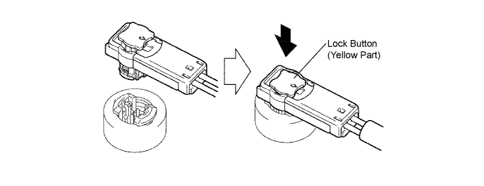
Connect the connector.
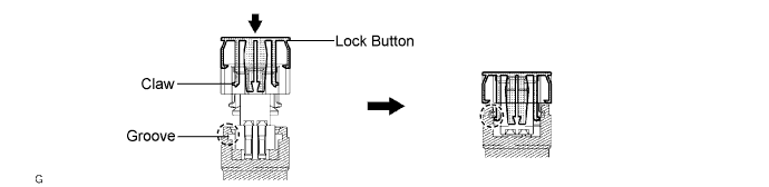
Push the lever in to connect the holder (with connectors). Check that it locks and that a "click" sound is heard.
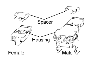
| 7.DISCONNECTION OF CONNECTOR FOR CENTER AIRBAG SENSOR |
Pull the lever by pushing the part labeled A and disconnect the holder (with connectors).
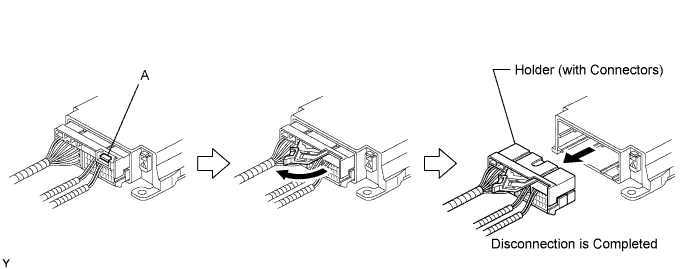
Replace the holder.
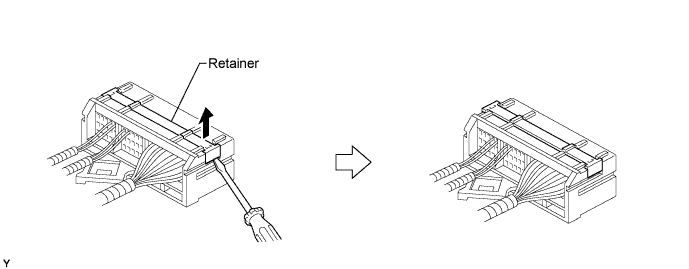
Using a screwdriver, unlock the retainer.
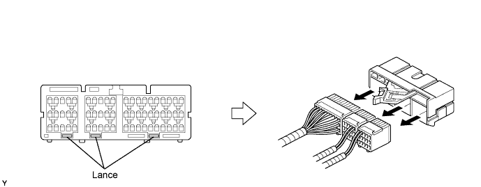
Release the lance fittings and remove the holder.
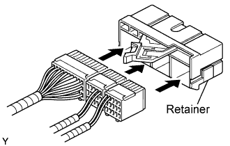 |
Install the connectors to a new holder. Check that they lock and that a "click" sound is heard.
Lock the retainer.
| 8.CONNECTION OF CONNECTOR FOR CENTER AIRBAG SENSOR |
Firmly insert the holder (with connectors) until it cannot be pushed any further.
Push the lever in to connect the holder (with connectors). Check that it locks and that a "click" sound is heard.
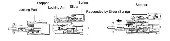
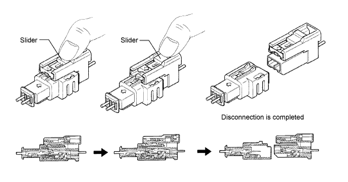
| 9.DISCONNECTION OF CONNECTOR FOR FRONT PASSENGER AIRBAG ASSEMBLY |
Place a finger on the slider.
Slide the slider to release the lock.
Disconnect the connector.
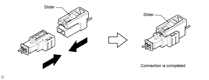
| 10.CONNECTION OF CONNECTOR FOR FRONT PASSENGER AIRBAG ASSEMBLY |
Connect the connector as shown in the illustration. Check that it locks and that a "click" sound is heard.
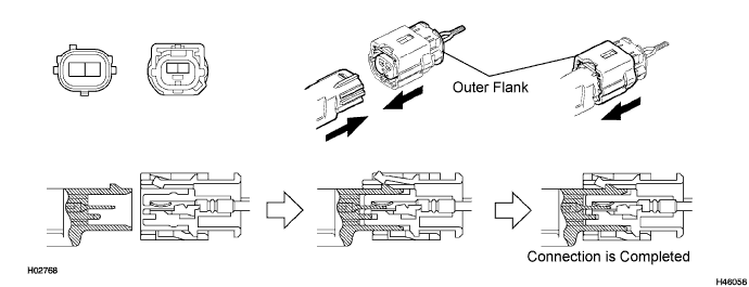
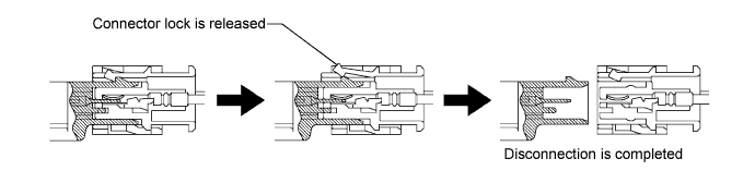
| 11.DISCONNECTION OF CONNECTOR FOR FRONT AIRBAG SENSOR (LH AND RH) |
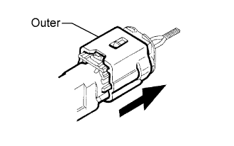 |
Hold the sides of the outer flank and slide it as shown in the illustration to release the connector lock.
Disconnect the connector.
| 12.CONNECTION OF CONNECTOR FOR FRONT AIRBAG SENSOR (LH AND RH) |
Connect the connector as shown in the illustration. Check that it locks and that a "click" sound is heard.