CAMSHAFT > INSTALLATION |
| 1. INSTALL CAMSHAFT TIMING GEAR |
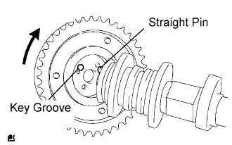 |
Put the camshaft timing gear and camshaft together by aligning the key groove and straight pin.
Check that there is no gap between the gear's flange and the camshaft.
With the camshaft timing gear fixed in place, tighten the flange bolt.
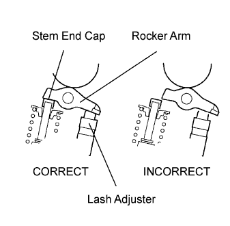
| 2. INSTALL VALVE STEM CAP |
Apply clean engine oil to the valve stem tip, and install the valve stem cap.
| 3. INSTALL VALVE LASH ADJUSTER |
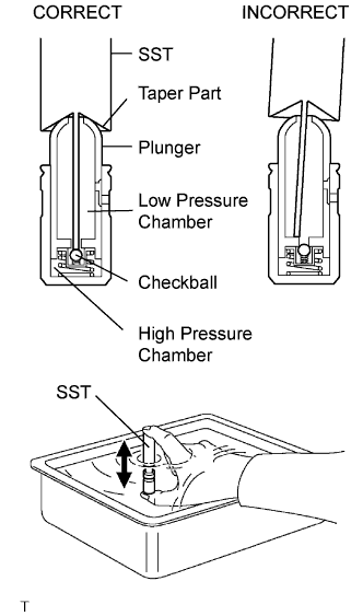 |
Place the lash adjuster into a container full of engine oil.
Insert SST's tip into the lash adjuster's plunger and use the tip to press down on the checkball inside the plunger.
Squeeze the SST and lash adjuster together to move the plunger up and down 5 to 6 times.
Check the movement of the plunger and bleed air.
After bleeding air, remove SST. Then, try to quickly and firmly press the plunger with a finger.
Install the lash adjuster.
| 4. INSTALL VALVE ROCKER ARM |
Apply clean engine oil to the valve lash adjuster tips and valve stem cap surfaces. Then install the valve rocker arms.
| 5. INSTALL CAMSHAFT |
 |
Apply clean engine oil to the camshaft's cam portion and the cylinder head journals.
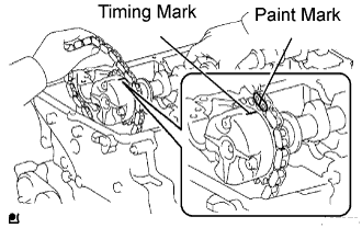
Install the timing chain on the camshaft timing gear, with the painted mark of the link aligned with the timing mark of the camshaft timing gear.
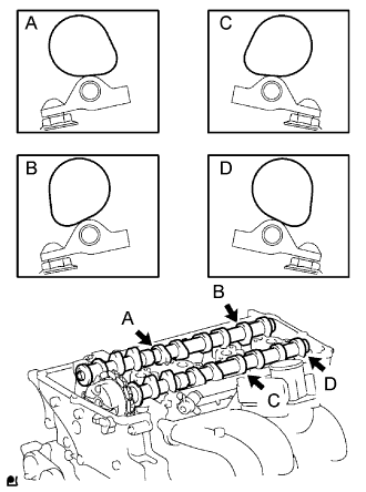 |
Set the 2 camshafts as shown in the illustration.
 |
 |
Loosely install the No. 1 camshaft bearing cap.
Check the proper location of each camshaft bearing cap and install each one.
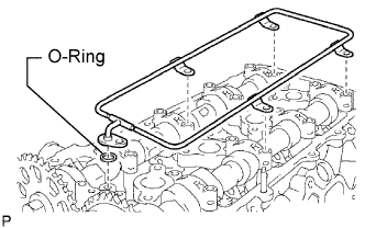 |
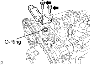
Install a new O-ring to the No. 1 camshaft bearing cap.
Temporarily install the oil delivery pipe.
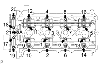 |
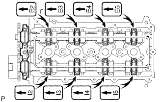
Tighten the 21 bolts and 20 washers in the order shown in the illustration.
| 6. INSTALL CAMSHAFT TIMING SPROCKET |
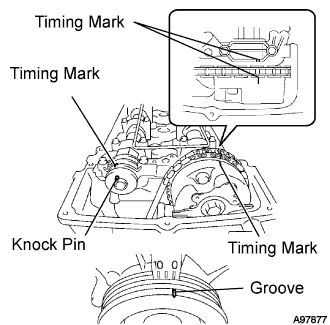 |
Rotate the camshaft so that the camshaft's timing mark and the No. 2 camshaft knock pin are as shown in the illustration.
Turn the crankshaft pulley, and align its groove with timing mark 0 of the timing chain cover.
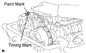 |
Install the timing chain on the camshaft timing sprocket, with the paint mark aligned with the timing marks on the camshaft timing sprocket.
Align the No. 2 camshaft knock pin and camshaft timing sprocket's pin hole. Then install the camshaft timing sprocket to the No. 2 camshaft.
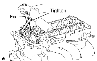 |
Fix the camshaft with a wrench, and then tighten the sprocket bolt.
Remove the hexagon wrench from the chain tensioner.
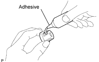 |
Apply adhesive to 2 or 3 threads of the timing chain cover plug.
Using a 10 mm socket hexagon wrench, install the timing gear case plug.
| 7. INSTALL TIMING CHAIN GUIDE |
 |
Install a new O-ring to the camshaft bearing cap.
Install the timing chain guide with the 2 bolts.
| 8. INSTALL CYLINDER HEAD COVER |
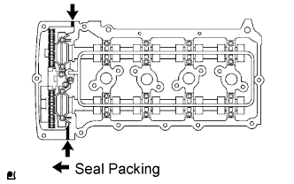 |
Install the 2 gaskets to the cylinder head cover.
Remove any old packing (FIPG) material.
Apply seal packing to 2 locations as shown in the illustration.
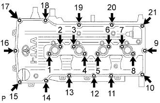 |
Loosely install the head cover with the 19 bolts and 2 nuts.
Uniformly tighten the 19 bolts and 2 nuts in the sequence shown in the illustration.
In numerical order, confirm that the bolts labeled 1 to 18 are tightened to the torque specification. Tighten the bolts as necessary.
Connect the wire harness to the 6 clamps.
| 9. INSTALL IGNITION COIL |
Install the ignition coil with the bolt.
| 10. INSTALL INTAKE AIR CONNECTOR |
Install the intake air connector with the 2 bolts, and tighten the 2 hose clamps.
| 11. INSTALL DRIVE BELT |
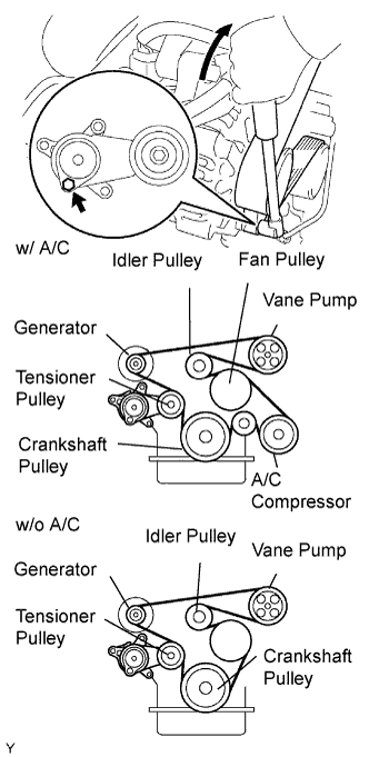 |
Install the drive belt to the pulleys except the drive belt tensioner pulley.
Use the hexagon-shaped part indicated by the arrow in the illustration to move the tensioner pulley downward and then install the drive belt to the tensioner pulley.
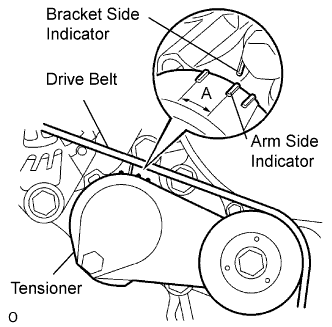 |
After a new belt has been installed, check that the tensioner indicator mark is within range A shown in the illustration.
| 12. CONNECT CABLE TO NEGATIVE BATTERY TERMINAL |
| 13. PERFORM INITIALIZATION |
Perform initialization (Click here).
| 14. CHECK FOR ENGINE OIL LEAKS |
Start the engine, and check that there are no oil leaks after performing maintenance.
| 15. CHECK FOR ENGINE COOLANT LEAKS |
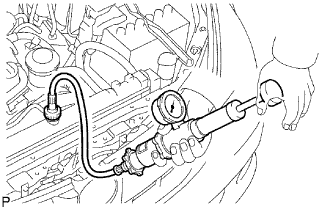 |
Fill the radiator with coolant and attach a radiator cap tester.
Warm up the engine.
Using the radiator cap tester, increase the pressure inside the radiator to 118 kPa (1.2 kgf/cm2, 17.1 psi), and check that the pressure does not drop.
If the pressure drops, check the hoses, radiator and water pump for leaks. If no external leaks are found, check the cylinder block and head.
| 16. INSPECT ENGINE IDLE SPEED AND IGNITION TIMING |
Warm up and stop the engine.
Check the idle speed control system.
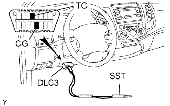 |
Using SST, connect terminals TC and CG of the DLC3.
Start the engine at idle.
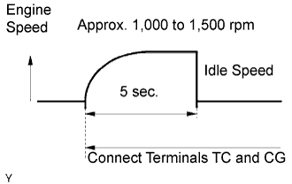 |
After connecting terminals (TC and CG), check that the engine speed changes to approximately 1,000 to 1,500 rpm for 5 seconds, and then returns to idle speed.
If the result is not as specified, check the throttle body, DTC (Click here) and wire harness.
| 17. CHECK CO/HC |
Start and warm up the engine.
Run the engine at 2,500 rpm for approximately 180 seconds and idle the engine.
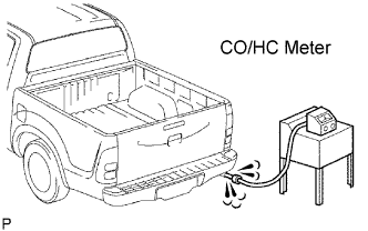 |
Insert CO/HC meter testing probe at least 40 cm (1.3 ft.) into the tailpipe.
Check CO/HC concentration at idle.
If the CO/HC concentration is not as specified, perform troubleshooting in the order given below.
Check the heated oxygen sensor operation (Click here).
See the table below for possible causes, and then inspect and repair the applicable causes if necessary.
| CO | HC | Problems | Causes |
| Normal | High | Rough idle |
|
| Low | High | Rough idle (Fluctuating HC reading) |
|
| High | High | Rough idle (Black smoke from exhaust) |
|
| 18. CHECK FUNCTION OF THROTTLE BODY |
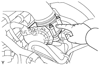 |
Check the throttle control motor operating sound.
Turn the ignition switch ON.
When pressing the accelerator pedal, check the operating sound of the running motor. Make sure that no friction noises emit from the motor.
If friction noise is heard, replace the throttle body.
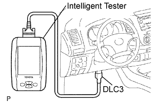 |
Check the throttle position sensor.
Connect the intelligent tester to the DLC3.
Turn the ignition switch ON.
Under Current Data, check that the throttle valve opening percentage (Throttle Pos) is within the standard.
