ENGINE UNIT > REASSEMBLY |
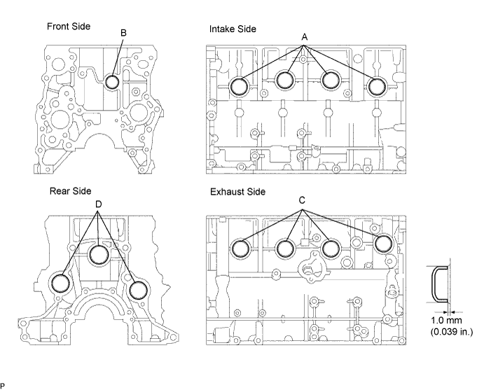
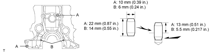
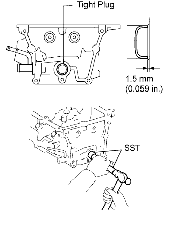
| 1. INSTALL TIGHT PLUG |
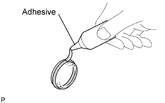 |
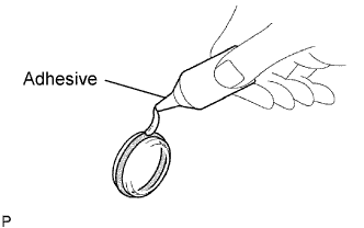
Apply adhesive around the tight plugs.
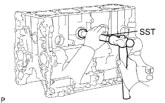 |
Using SST and a hammer, tap in new tight plugs as shown in the illustration.
Using SST, tap in the 8 tight plugs A and C.
Using SST, tap in the tight plug B.
Using SST, tap in the 3 tight plugs D.
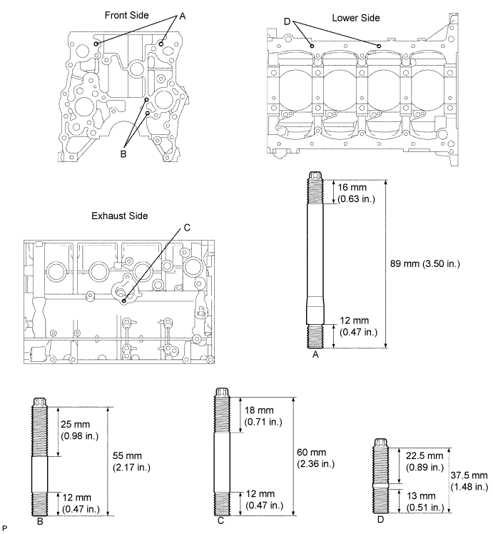
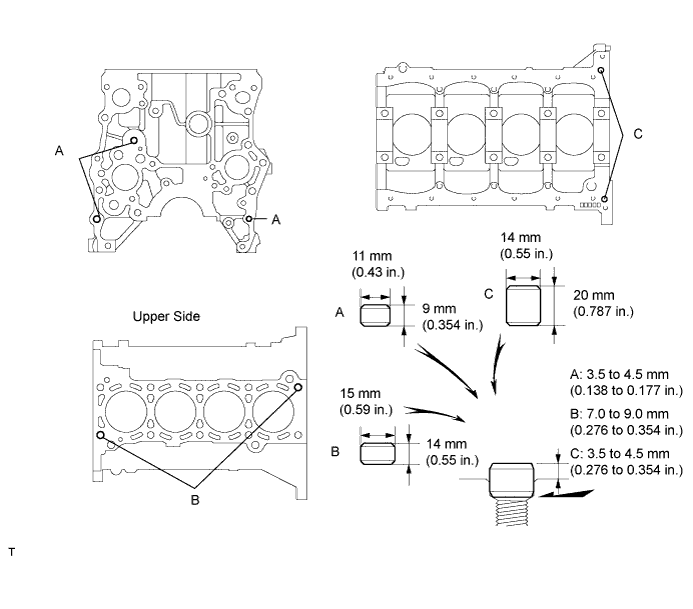
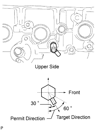
| 2. INSTALL STUD BOLT |
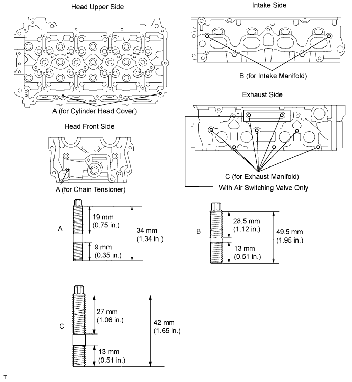
Using an E7 "torx" socket wrench, install the stud bolts B and D.
Using an E8 "torx" socket wrench, install the stud bolts A.
Apply adhesive to the hole for the stud bolt C on the cylinder block. Using an E7 "torx" socket wrench, install the stud bolt C.
| 3. INSTALL STRAIGHT PIN |
Using a plastic-faced hammer, tap in new straight pins to the cylinder block.
| 4. INSTALL RING PIN |
Using a plastic-faced hammer, tap in new ring pins to the cylinder block.
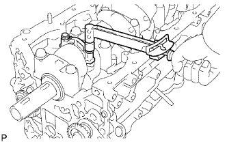
| 5. INSTALL NO. 2 BALANCE SHAFT DRIVEN GEAR |
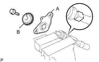 |
Mount the head portion of the balance shaft in a vise.
Install the No. 2 balance shaft thrust washer (labeled A) and balance shaft No. 2 driven gear (labeled B).
Install and torque the bolt.
| 6. INSTALL NO. 2 BALANCE SHAFT |
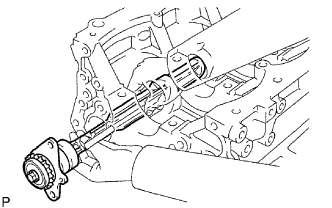 |
Install the balance shaft to the cylinder block.
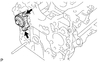 |
Install the 2 bolts.
| 7. INSTALL NO. 1 BALANCE SHAFT DRIVEN GEAR |
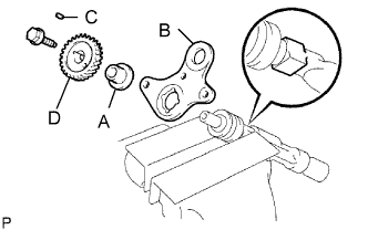 |
Mount the head portion of the balance shaft in a vise.
Install the balance shaft thrust spacer (labeled A), No. 1 balance shaft thrust washer (labeled B), sliding key (labeled C) and No. 1 balance shaft driven gear (labeled D).
Install the bolt.
| 8. INSTALL NO. 1 BALANCE SHAFT |
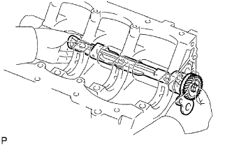 |
Install the No. 1 balance shaft to the cylinder block.
 |
Install and torque the bolt.
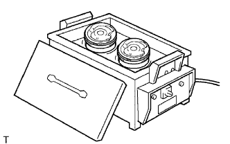
| 9. INSTALL OIL NOZZLE |
 |
Using an E7 "torx" socket wrench, install the oil nozzle.
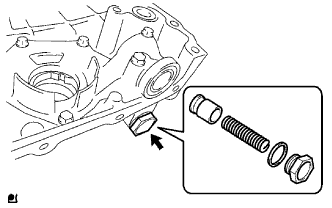
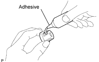
| 10. INSTALL CYLINDER BLOCK WATER DRAIN COCK |
 |
Apply adhesive around the drain cock.
 |
Install the cylinder block water drain cock as shown in the illustration.
Install the water drain cock plug to the water drain cock.
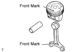
| 11. INSTALL PISTON WITH PIN |
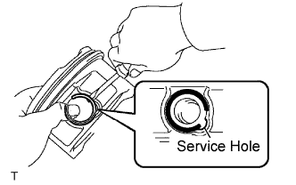 |
Assemble the piston and connecting rod.
Using a small screwdriver, install a new snap ring at one end of the piston pin hole.
 |
Gradually heat the piston to approximately 80 to 90°C (176 to 194°F).
 |
Coat the piston pin with engine oil.
Align the front marks of the piston and connecting rod, and push in the piston pin with your thumb.
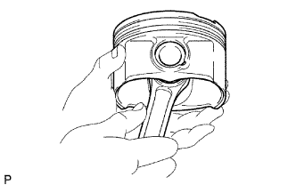 |
Check the fit between the piston and piston pin by trying to move the piston back and forth on the piston pin.
|
Using a small screwdriver, install a new snap ring at the other end of the piston pin hole.
 |
Install the piston rings.
Install the oil ring expander and 2 side rails by hand.
Using a piston ring expander, install the 2 compression rings with the painted mark as shown in the illustration.
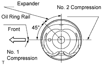 |
Position the piston rings so that the ring ends are as shown in the illustration.
| 12. INSTALL CONNECTING ROD BEARING |
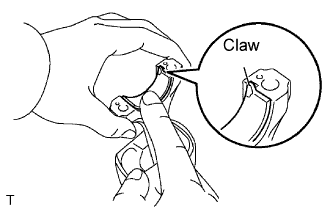 |
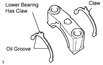
Align the bearing claw with the groove of the connecting rod or connecting cap.
Install the bearings in the connecting rod and connecting rod cap.
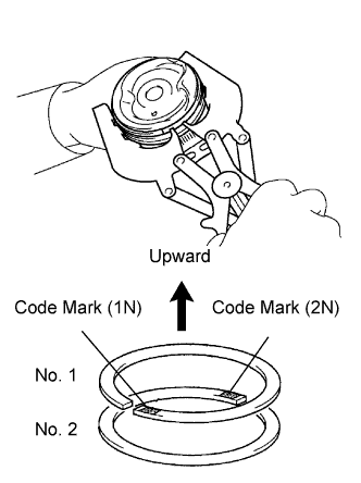
| 13. INSTALL CRANKSHAFT BEARING |
Clean the main journal, and the interior and exterior of the bearing.
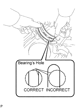 |
Install the upper bearing.
Install the upper bearing to the cylinder block so that the upper bearing's lubrication hole is centered within the cylinder block's lubrication hole, as shown in the illustration.
| Journal | Dimension (A) |
| # 1, 5 | 3.75 mm (0.1476 in.) |
| # 3 | 1.75 mm (0.0689 in.) |
| # 2, 4 | 2.75 mm (0.1083 in.) |
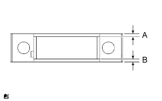 |
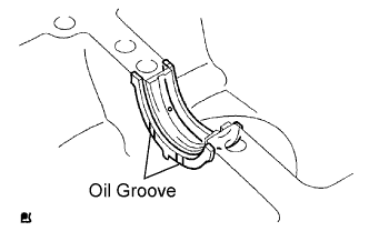
Install the lower bearing.
Install the lower bearing to the bearing cap.
Using a vernier caliper, measure the distance between the bearing cap's edge and the lower bearing's edge.
| Journal | Dimension |
| # 1, 5 | 3.83 mm (0.1508 in.) |
| # 3 | 1.74 mm (0.0685 in.) |
| # 2, 4 | 2.75 mm (0.1083 in.) |
With the upper bearing and lower bearing installed, use a plastic-faced hammer to install the bearing caps to the cylinder block.
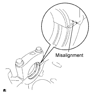 |
Using a vernier caliper, measure the amount of misalignment between the upper bearing and lower bearing, as shown in the illustration.
Remove the bearing cap.
| 14. INSTALL CRANKSHAFT |
 |
Install the crankshaft thrust washer upper to the cylinder block.
Install the 2 thrust washers under the No. 3 journal position of the cylinder block with the oil grooves facing outward.
 |
Install the 2 thrust washers on the No. 3 bearing cap with the grooves facing outward.
Apply engine oil to the upper bearing, then place the crankshaft on the cylinder block.
Apply engine oil to the lower bearing.
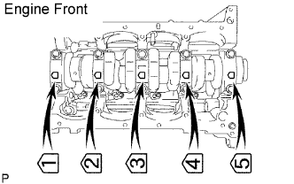 |
Install the 5 crankshaft bearing caps in their proper locations.
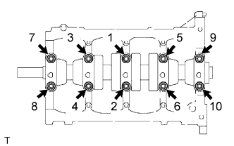 |
Install the crankshaft bearing cap bolts.
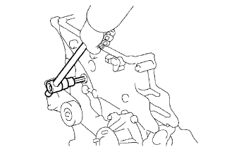
Install and uniformly tighten the 10 main bearing cap bolts in the sequence shown in the illustration.
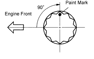 |
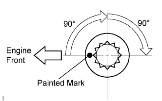
Mark the front of the bearing cap bolts with paint.
Retighten the bearing cap bolts by 90° in the numerical order above.
Check that the painted mark is now at a 90° angle to the front.
Check that the crankshaft turns smoothly.
Check the crankshaft thrust clearance.
| 15. INSTALL PISTON WITH CONNECTING ROD |
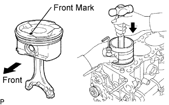 |
Using a piston ring compressor, push the correctly numbered piston and connecting rod assembly into the cylinder with the front mark of the piston facing forward.
Match the numbered connecting rod cap with the connecting rod.
Align the pins of the connecting rod cap with the pin holes of the connecting rod, and install the connecting rod cap.
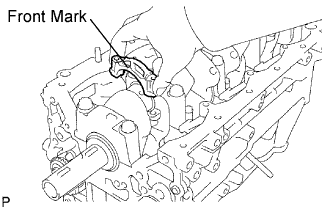 |
Check that the front mark of the connecting rod cap is facing forward.
 |
Install the connecting rod cap bolts.
Apply a light coat of engine oil on the threads and under the heads of the connecting rod cap bolts.
Install and alternately tighten the bolts of the connecting rod cap in several passes.
|
Mark the front of the connecting rod cap bolts with paint.
Retighten the connecting rod cap bolts 90° as shown.
Check that the painted mark is now at a 90° angle to the front.
Check that the crankshaft turns smoothly.
Check the connecting rod thrust clearance.
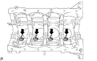
| 16. INSTALL RING PIN |
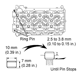 |
Using a plastic-faced hammer, tap in a new ring pin until the pin stops.
| 17. INSTALL NO. 1 HEAD STRAIGHT SCREW PLUG |
 |
Using a 10 mm hexagon wrench, install a new gasket and the straight screw plug.
| 18. INSTALL NO. 2 HEAD STRAIGHT SCREW PLUG |
 |
Using a 19 mm hexagon wrench, install a new gasket and the straight screw plug.
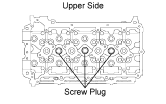
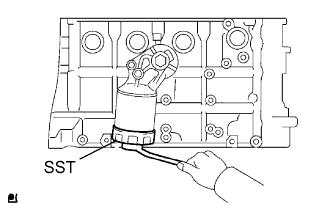
| 19. INSTALL TIGHT PLUG |
 |
Apply adhesive to the tight plug hole of the cylinder head.
 |
Using SST, tap in a new tight plug to the cylinder head as shown in the illustration.
| 20. INSTALL STUD BOLT |
Using E5 and E7 "torx" socket wrenches, install the stud bolts.
| 21. INSTALL OIL CONTROL VALVE FILTER |
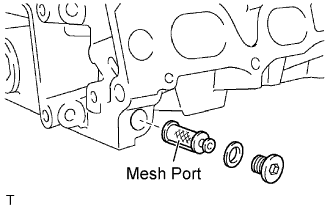 |
Check that no foreign matter is on the mesh part of the filter.
If foreign objects are present, clean the part thoroughly.
Using a 6 mm hexagon wrench, install a new gasket and the oil control valve filter with the screw plug.
| 22. INSTALL VALVE SPRING SEAT |
| 23. INSTALL VALVE STEM OIL SEAL |
 |
Apply a light coat of engine oil on a new oil seal.
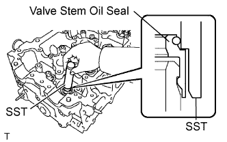 |
Using SST, push in the oil seal.
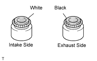
| 24. INSTALL INTAKE VALVE |
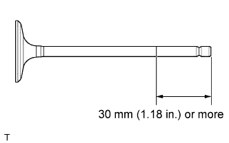 |
Apply plenty of engine oil to the tip area of the intake valve indicated in the illustration.
 |
Install the valve, spring seat, compression spring and spring retainer to the cylinder head.
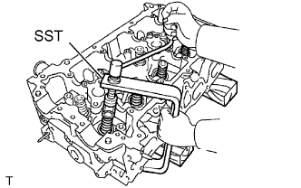 |
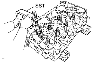
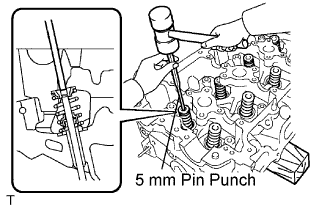
Using SST and wooden blocks, compress the spring and install the 2 retainer locks.
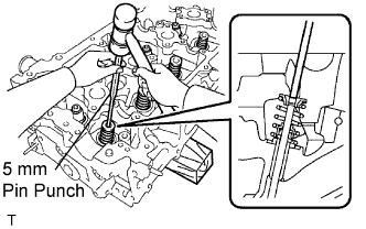 |
Using a 5 mm pin punch and plastic-faced hammer, lightly tap the valve stem tip to ensure a proper fit.
| 25. INSTALL EXHAUST VALVE |
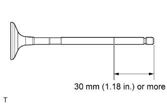 |
Apply plenty of engine oil to the tip area of the intake valve indicated in the illustration.
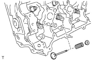 |
Install the valve, spring seat, compression spring and spring retainer to the cylinder head.
 |
Using SST and wooden blocks, compress the spring and install the 2 retainer locks.
 |
Using a 5 mm pin punch and plastic-faced hammer, lightly tap the valve stem tip to ensure a proper fit.
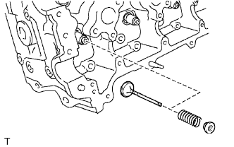
| 26. INSTALL VALVE LASH ADJUSTER |
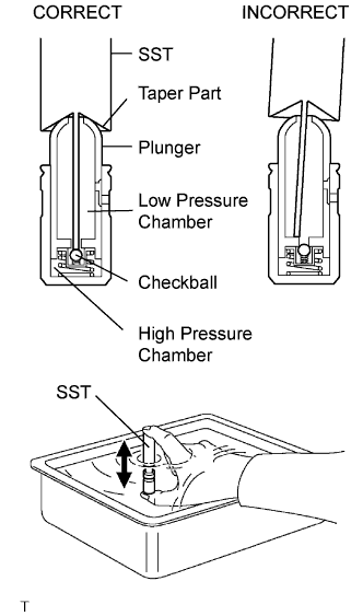 |
Place the lash adjuster into a container full of engine oil.
Insert SST's tip into the lash adjuster's plunger and use the tip to press down on the checkball inside the plunger.
Squeeze the SST and lash adjuster together to move the plunger up and down 5 to 6 times.
Check the movement of the plunger and bleed air.
After bleeding air, remove SST. Then, try to quickly and firmly press the plunger with a finger.
| 27. INSTALL VALVE STEM CAP |
Apply a light coat of engine oil to the valve stem cap.
Install the valve stem cap to the cylinder head.
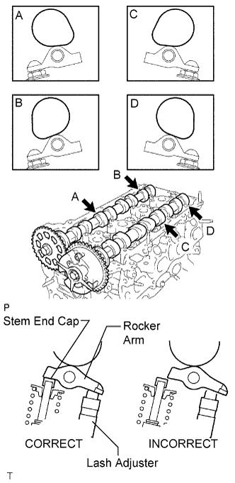
| 28. INSTALL VALVE ROCKER ARM |
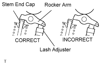 |
Apply clean engine oil to the valve lash adjuster tip and valve stem cap surface. Then install the valve rocker arm.
| 29. INSTALL CRANKSHAFT PULLEY SET KEY |
 |
Install the 2 pulley keys to the crankshaft.
| 30. INSTALL NO. 4 CHAIN VIBRATION DAMPER |
 |
Install the No. 4 vibration damper with the 2 bolts.
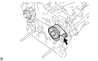
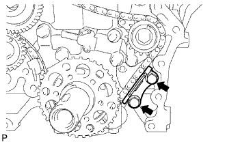
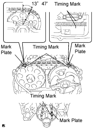
| 31. INSTALL NO. 2 CHAIN |
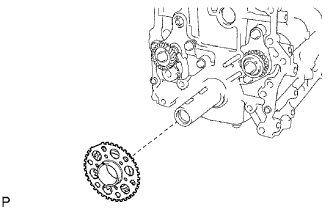 |
Install the No. 2 timing sprocket as shown in the illustration.
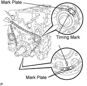 |
As shown in the illustration, install the chain on the sprocket and gear with the painted marks aligned with the timing marks on the sprocket and gear.
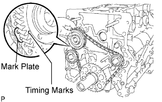 |
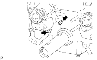
Fit the other mark link of the crankshaft timing sprocket behind the large timing mark of the balance shaft drive gear.
Insert the balance shaft drive gear shaft through the balance shaft drive gear so that it fits into the thrust plate hole.
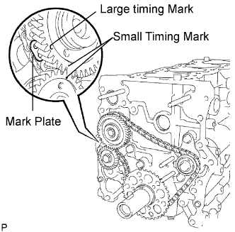 |
Align the small timing mark of the balance shaft drive gear with the timing mark of the balance shaft timing gear.
Install the bolt to the balance shaft drive gear and tighten it.
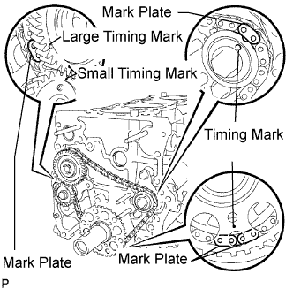 |
Check that each timing mark is matched with the corresponding mark link.
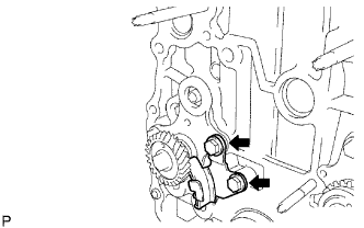
| 32. INSTALL NO. 2 CHAIN TENSIONER |
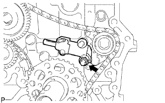 |
Install the No. 2 chain tensioner with the nut.
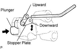 |
Move the stopper plate downward to release the lock, and push the plunger deep into the tensioner.
Move the stopper plate upward to set the lock, and insert a hexagon wrench into the stopper plate's hole.
| 33. INSTALL NO. 3 CHAIN VIBRATION DAMPER |
 |
Install the No. 3 chain vibration damper with the 2 bolts.
| 34. INSTALL NO. 2 CHAIN VIBRATION DAMPER |
 |
Install the No. 2 chain vibration damper with the bolt.
Remove a pin from the No. 2 chain tensioner and release the plunger.
| 35. INSTALL ENGINE REAR OIL SEAL RETAINER |
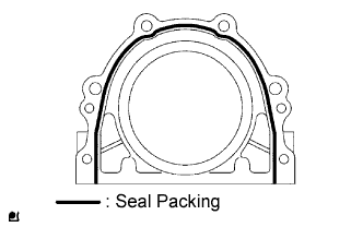 |
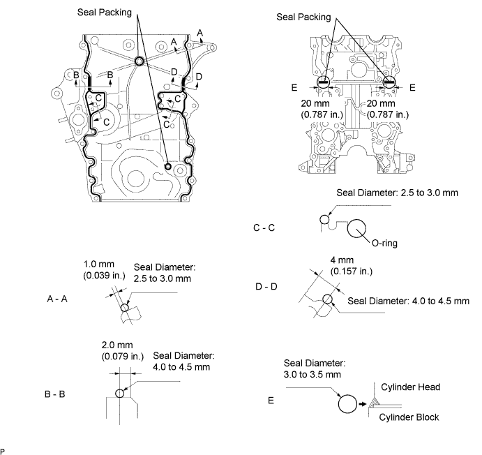
Apply seal packing in a continuous line to the places shown in the illustration.
Install the oil seal with the 6 bolts.
| 36. INSTALL OIL FILTER BRACKET |
Install a new O-ring to the oil filter bracket.
Install a new O-ring and gasket to the oil filter bracket union bolt.
Install the oil filter bracket with the oil filter union bolt and nut.
| 37. INSTALL OIL FILTER UNION |
Using a 27 mm socket wrench, install the oil filter union.
| 38. INSTALL OIL FILTER |
 |
Check and clean the oil filter installation surface.
Apply clean engine oil to the gasket of a new oil filter.
Lightly screw the oil filter into place, and tighten it until the gasket contacts the seat.
Using SST, tighten the oil filter.
When using a torque wrench: Using a torque wrench to tighten the oil filter.
When not using a torque wrench: Tighten the oil filter a 3/4 turn by a common wrench.
| 39. INSTALL CYLINDER HEAD GASKET |
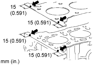 |
Apply seal packing to the cylinder block upper side and cylinder head gasket upper side as shown in the illustration.
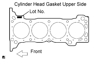 |
Place a new cylinder head gasket on the cylinder block surface with the Lot No. stamp upward.
| 40. INSTALL CYLINDER HEAD |
Place the cylinder head on the cylinder block.
Apply a light coat of engine oil on the threads and under the heads of the cylinder head bolts.
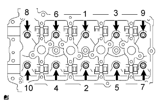 |
Using a 10 mm bi-hexagon wrench, install and uniformly tighten the 10 cylinder head bolts with the plate washers, in several passes, in the sequence shown.
 |
Mark the front of the cylinder head bolt head with paint.
Retighten the cylinder head bolts by 90° in the numerical order shown.
Retighten the cylinder head bolts by an additional 90°.
Check that the painted mark is now facing rearward.
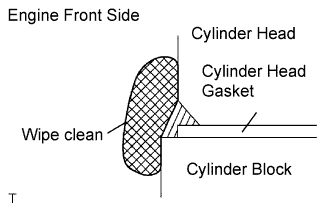 |
Seal packing will seep out on the engine's front side. Thoroughly wipe clean any seal packing.
| 41. INSTALL CAMSHAFT TIMING GEAR |
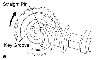 |
Put the camshaft timing gear and camshaft together by aligning the key groove and straight pin.
Check that there is no gap between the gear's flange and the camshaft.
With the camshaft timing gear fixed in place, tighten the flange bolt.
| 42. INSTALL CAMSHAFT TIMING SPROCKET |
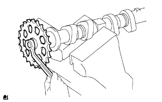 |
Clamp the camshaft in a vise and then install the camshaft timing sprocket to the camshaft with the sprocket bolt.
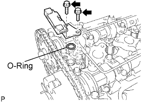
| 43. INSTALL CAMSHAFT |
 |
Apply clean engine oil to the camshaft's cam portion and the cylinder head journals.
Set the camshaft and No. 2 camshaft as shown in the illustration.
 |
Loosely install the No. 1 camshaft bearing cap.
Check the proper location of each No. 2 camshaft bearing cap and install each one.
 |
Install a new O-ring to the No. 1 camshaft bearing cap.
Loosely install the oil delivery pipe.
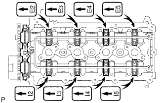
 |
Tighten the 21 bolts and 20 washers in the order shown in the illustration.
| 44. INSTALL OIL JET |
Install a new gasket and the oil jet with the bolt.
| 45. INSTALL CRANKSHAFT PULLEY SET KEY |
Install the 2 pulley keys to the crankshaft.
| 46. INSTALL CRANKSHAFT TIMING SPROCKET |
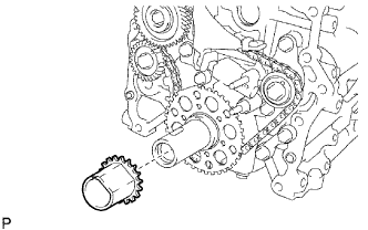 |
Install the timing sprocket as shown in the illustration.
| 47. INSTALL CHAIN VIBRATION DAMPER |
 |
Install the vibration damper with the bolt and nut.
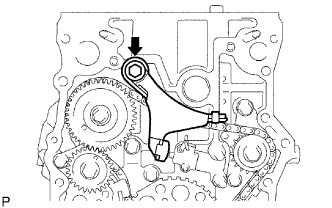
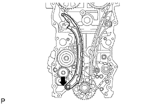
| 48. INSTALL CHAIN |
 |
As shown in the illustration, install the chain on the sprocket and gear with the painted marks aligned with the timing marks on the sprocket and gear.
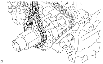 |
Use a rope to tie the chain of the crankshaft timing sprocket. Tie the rope near the sprocket.
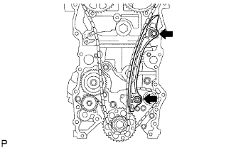
| 49. INSTALL CHAIN TENSIONER SLIPPER |
 |
Install the tensioner slipper with the bolt.
| 50. INSTALL CHAIN TENSIONER |
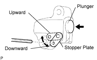 |
Move the stopper plate upward to release the lock, and push the plunger deep into the tentioner.
Move the stopper plate downward to set the lock, and insert a hexagon wench into the stopper plate's hole.
 |
Install a new gasket and the chain tensioner with the bolt and nut.
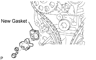
| 51. INSTALL TIMING CHAIN GUIDE |
 |
Install a new O-ring and the chain guide with the 2 bolts.
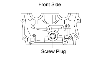
| 52. INSTALL OIL PUMP RELIEF VALVE |
 |
Coat the relief valve with engine oil.
Insert the relief valve and spring into the pump body hole.
Install a new gasket to the plug.
Using a 27 mm socket wrench, install the plug.
| 53. INSTALL WATER PUMP |
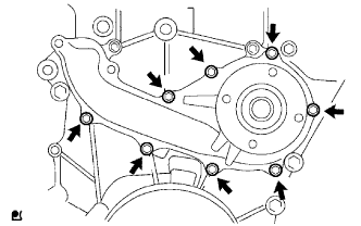 |
Install a new gasket and the water pump with the 8 bolts.
| 54. INSTALL TIMING CHAIN COVER |
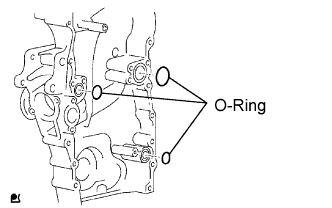 |
Install 3 new O-rings to the timing chain cover as shown in the illustration.
 |
Apply adhesive to the timing gear case plug.
 |
Using a 10 mm socket hexagon wrench, install the timing chain cover plug.
Apply seal packing in a continuous to the places shown in the illustration.
| Position | Specified Condition |
| A - A, C - C | 2.5 to 3.0 mm (0.098 to 0.118 in.) |
| B - B, D - D | 4.0 to 4.5 mm (0.157 to 0.177 in.) |
| E | 3.0 to 3.5 mm (0.118 to 0.138 in.) |
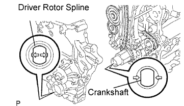 |
Align the oil pump's drive rotor spline and the crankshaft as shown in the illustration. Install the spline and chain cover to the crankshaft.
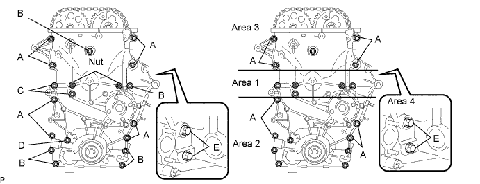
Loosely install the timing chain cover with the 19 bolts and nut, but do not tighten the bolts and nuts yet.
Excluding bolt A, fully tighten the bolts and nuts in this order: Area 1, Area 2 and Area 3.
Fully tighten the bolts labeled A in this order: Area 2 and Area 3.
Fully tighten the bolts labeled E for Area 4.
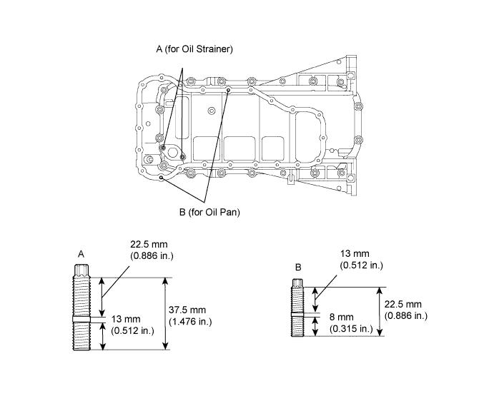
| 55. INSTALL NO. 1 OIL PAN |
Install the stud bolt.
Using an E5 "torx" socket wrench, install the stud bolts labeled A for the oil pan as shown in the illustration.
Using an E7 "torx" socket wrench, install the stud bolts labeled B for the oil strainer as shown in the illustration.
|
Install a new tight plug.
Apply adhesive around a new tight plug.
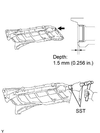 |
Using SST and hammer, install the tight plug as shown in the illustration.
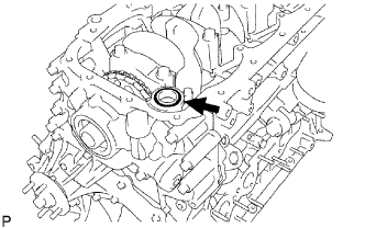 |
Install a new O-ring.
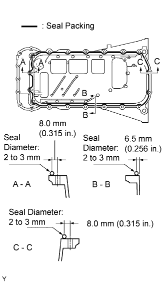 |
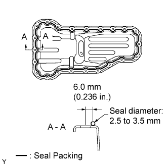
Apply seal packing in a continuous line to the places shown in the illustration.
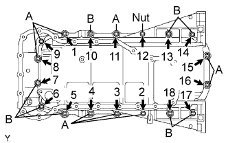 |
Temporarily install the oil pan with the 16 bolts and 2 nuts.
Uniformly tighten the 16 bolts and 2 nuts in the sequence shown in the illustration.
| 56. INSTALL OIL STRAINER |
Install a new gasket and the oil strainer with the bolt and 2 nuts.
| 57. INSTALL NO. 2 OIL PAN |
 |
Apply seal packing in a continuous line to the places shown in the illustration.
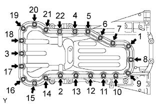 |
Temporarily install the oil pan with the 20 bolts and 2 nuts.
Uniformly tighten the 20 bolts and 2 nuts in the sequence shown in the illustration.
Install a new gasket and the drain plug.
| 58. INSTALL CRANKSHAFT PULLEY |
Align the pulley set key with the key groove of the pulley, and slide on the pulley.
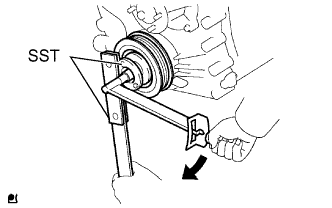 |
Using SST, install a new pulley bolt.
| 59. INSTALL CYLINDER HEAD COVER |
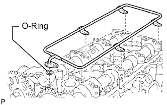
Install the 2 gaskets to the head cover.
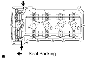 |
Apply seal packing to the places shown in the illustration.
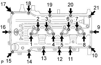 |
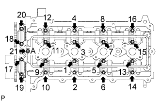
Temporarily install the cover with the 19 bolts and 2 nuts.
Uniformly tighten the 19 bolts and 2 nuts in the sequence shown in the illustration.
In numerical order, confirm that the bolts labeled 1 to 8 are tighten to the torque specification. Tighten the bolts as necessary.
| 60. INSTALL VENTILATION VALVE |
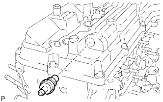 |
Install the ventilation valve to the head cover.
| 61. INSTALL OIL FILLER CAP |
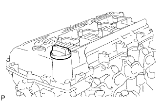 |
Install the oil filler cap assembly.
