ENGINE UNIT > DISASSEMBLY |
| 1. REMOVE OIL FILLER CAP |
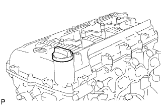 |
Remove the oil filler cap from the head cover.
| 2. REMOVE VENTILATION VALVE |
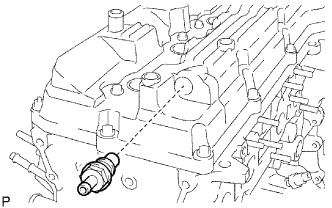 |
Remove the ventilation valve from the head cover.
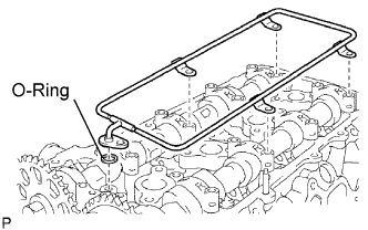
| 3. REMOVE CYLINDER HEAD COVER |
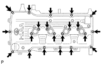 |
Remove the 19 bolts, 2 nuts, cover and 2 gaskets.
| 4. REMOVE CRANKSHAFT PULLEY |
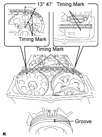 |
Turn the crankshaft pulley, and align its groove with timing mark 0 of the timing chain cover.
Check that the timing marks of the camshaft timing gear and sprocket are aligned with the timing marks of the No. 1 bearing cap, as shown in the illustration.
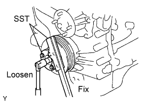 |
Using SST, hold the crankshaft pulley and remove the pulley set bolt.
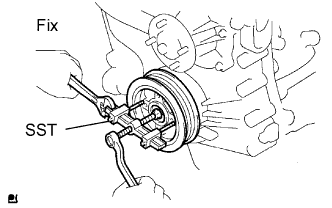 |
Using the set bolt and SST, remove the pulley bolt and pulley.
| 5. REMOVE NO. 2 OIL PAN |
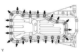 |
Remove the drain plug and gasket.
Remove the 20 bolts and 2 nuts.
 |
Insert the blade of SST between the oil pans. Cut through the applied sealer and remove the oil pan.
| 6. REMOVE OIL STRAINER |
Remove the bolt, 2 nuts, oil strainer and gasket.
| 7. REMOVE NO. 1 OIL PAN |
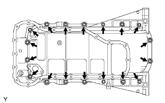 |
Remove the 16 bolts and 2 nuts.
 |
Remove the oil pan by prying between the oil pan and cylinder block with a screwdriver.
 |
Remove the O-ring.
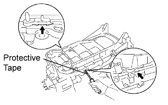
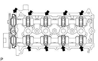
| 8. REMOVE TIMING CHAIN COVER |
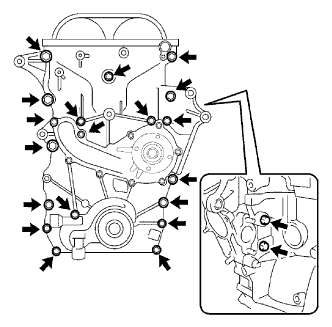 |
Remove the 19 bolts and 2 nuts as shown in the illustration.
 |
Remove the timing chain cover by prying between the timing chain cover and cylinder head or cylinder block with a screwdriver.
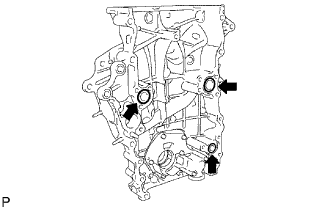 |
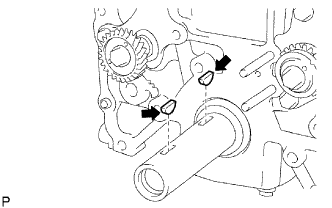
Remove the 3 O-rings.
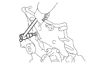 |
Using a 10 mm socket hexagon wrench, remove the timing chain cover plug.
| 9. REMOVE WATER PUMP |
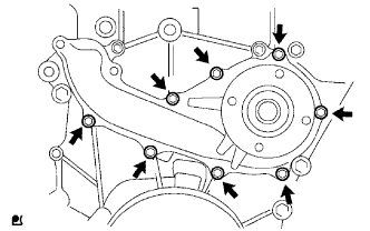 |
Remove the 8 bolts, water pump and gasket.
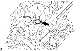
| 10. REMOVE TIMING CHAIN COVER OIL SEAL |
 |
Using a screwdriver with its tip taped, pry out the oil seal.
| 11. REMOVE OIL PUMP RELIEF VALVE |
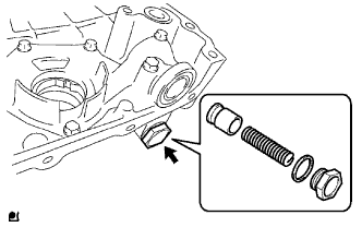 |
Using a 27 mm socket wrench, remove the plug and gasket.
Remove the valve spring and relief valve.
| 12. REMOVE TIMING CHAIN GUIDE |
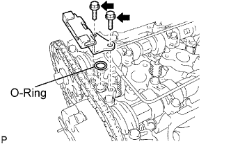 |
Remove the 2 bolts, timing chain guide and O-ring.
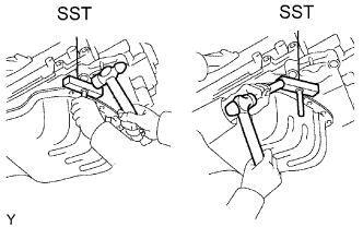
| 13. REMOVE NO. 1 TIMING CHAIN TENSIONER |
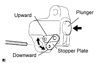 |
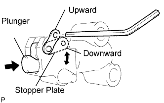
Move the stopper plate upward to release the lock, and push the plunger deep into the tensioner.
Move the stopper plate downward to set the lock, and insert a hexagon wrench into the stopper plate's hole.
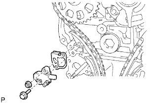 |
Remove the bolt, nut, chain tensioner and gasket.
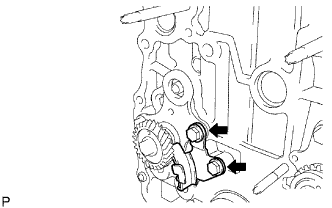
| 14. REMOVE CHAIN TENSIONER SLIPPER |
 |
Remove the bolt and tensioner slipper.
| 15. REMOVE NO. 1 VIBRATION DAMPER |
 |
Remove the bolt, nut and vibration damper.
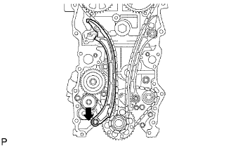
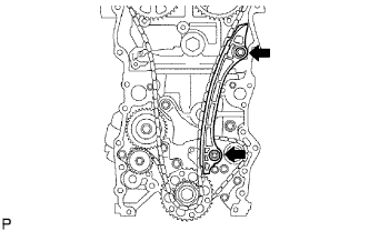
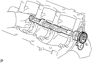
| 16. REMOVE TIMING CHAIN |
| 17. REMOVE CRANKSHAFT TIMING SPROCKET |
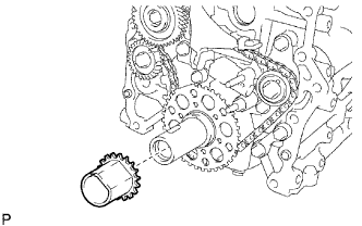 |
Remove the crankshaft timing sprocket from the crankshaft.
| 18. REMOVE CRANKSHAFT POSITION SENSOR PLATE |
| 19. REMOVE OIL JET |
Remove the bolt, oil jet and gasket.
| 20. REMOVE CAMSHAFT |
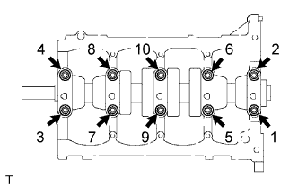
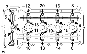 |
Uniformly loosen the 21 bearing cap bolts in the several passes in the order shown in the illustration.
Remove the 9 bearing caps, oil delivery pipe, O-ring and 2 camshafts.
 |
Remove the oil delivery pipe and O-ring from the bearing caps.
 |
Remove the 9 bearing caps.
Remove the 2 camshafts.
| 21. REMOVE CAMSHAFT TIMING SPROCKET |
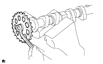 |
Fix the camshaft with a vise and then remove the sprocket bolt and camshaft timing sprocket.
| 22. REMOVE CAMSHAFT TIMING GEAR |
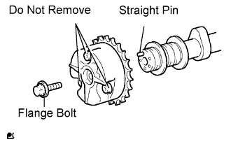 |
Remove the flange bolt of the camshaft timing gear.
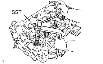
| 23. REMOVE CYLINDER HEAD |
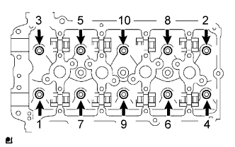 |
Using a 10 mm bi-hexagon wrench, uniformly loosen the 10 bolts in the sequence shown in the illustration. Remove the 10 cylinder head bolts and plate washers.
Remove the cylinder head and gasket.
| 24. REMOVE NO. 2 CHAIN VIBRATION DAMPER |
 |
Move the stopper plate downward to release the lock, and push the plunger deep into the tensioner.
Move the stopper plate upward to set the lock, and insert a hexagon wrench into the stopper plate's hole.
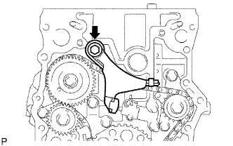 |
Remove the bolt and chain vibration damper.
| 25. REMOVE NO. 3 CHAIN VIBRATION DAMPER |
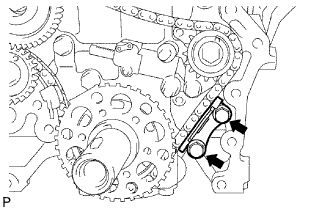 |
Remove the 2 bolts and chain vibration damper.
| 26. REMOVE NO. 2 CHAIN TENSIONER |
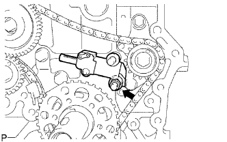 |
Remove the hexagon wrench from the tensioner.
Remove the nut and chain tensioner.
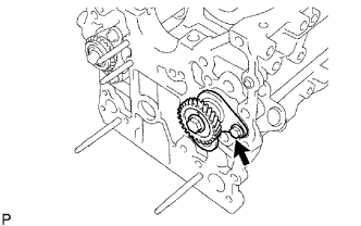
| 27. REMOVE NO. 2 CHAIN |
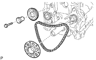 |
Remove the bolt, balance shaft drive gear shaft and balance shaft drive gear.
Remove the No. 2 crankshaft timing sprocket and chain.
| 28. REMOVE NO. 4 CHAIN VIBRATION DAMPER |
 |
Remove the 2 bolts and No. 4 vibration damper.
| 29. REMOVE CRANKSHAFT PULLEY SET KEY |
 |
Remove the 2 pulley set keys from the crankshaft.
| 30. REMOVE OIL FILTER |
 |
Using SST, remove the oil filter.
| 31. REMOVE OIL FILTER UNION |
Using a 27 mm socket wrench, remove the oil filter union.
| 32. REMOVE OIL FILTER BRACKET |
Remove the oil filter bracket union bolt, gasket and oil filter union.
Remove the oil filter bracket and O-ring.
Remove the O-ring from the oil filter bracket union bolt.
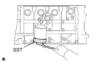
| 33. REMOVE ENGINE REAR OIL SEAL RETAINER |
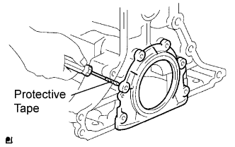 |
Remove the 6 bolts.
Using a screwdriver with its tip taped, pry out the oil seal retainer.
| 34. REMOVE VALVE ROCKER ARM |
| 35. REMOVE VALVE STEM CAP |
| 36. REMOVE VALVE LASH ADJUSTER |
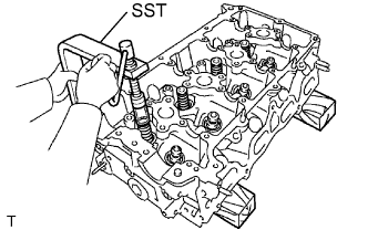
| 37. REMOVE INTAKE VALVE |
 |
Using SST and wooden blocks, compress the compression spring and remove the valve retainer locks.
 |
Remove the retainer, compression spring, valve, valve spring and spring seat.
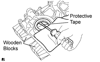
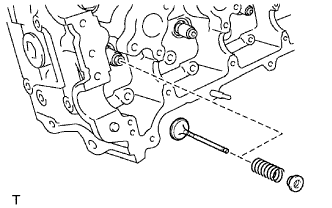
| 38. REMOVE EXHAUST VALVE |
 |
Using SST and wooden blocks, compress the compression spring and remove the valve retainer locks.
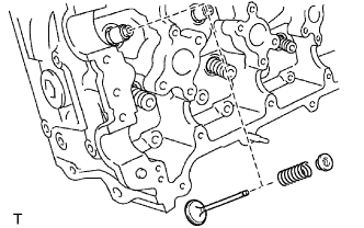 |
Remove the retainer, compression spring, valve, valve spring and spring seat.
| 39. REMOVE VALVE STEM OIL SEAL |
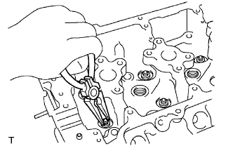 |
Using needle-nose pliers, remove the oil seal.
| 40. REMOVE OIL CONTROL VALVE FILTER |
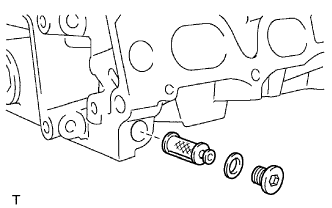 |
Using an 8 mm hexagon wrench, remove the screw plug.
Remove the oil control valve filter and gasket.
| 41. REMOVE NO. 1 HEAD STRAIGHT SCREW PLUG |
 |
Using a 10 mm hexagon wrench, remove the 3 screw plugs.
| 42. REMOVE NO. 2 HEAD STRAIGHT SCREW PLUG |
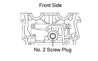 |
Using a 9 mm hexagon wrench, remove the screw plug.
| 43. REMOVE CONNECTING ROD CAP |
Check that the matchmarks on the connecting rod and cap are aligned to ensure the correct reassembly.
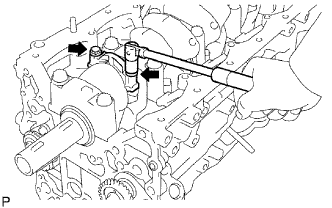 |
Remove the 10 connecting rod cap bolts.
Using the 2 removed connecting rod cap bolts, remove the connecting rod cab and lower bearing by wiggling the connecting rod cap right and left.
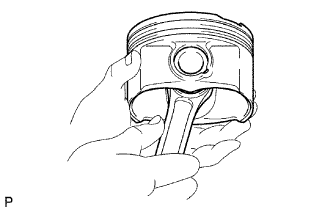
| 44. REMOVE PISTON WITH CONNECTING ROD |
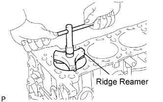 |
Using a ridge reamer, remove all the carbon from the top of the cylinder.
Push the piston, connecting rod assembly and upper bearing through the top of the cylinder block.
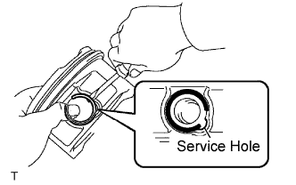
| 45. REMOVE PISTON PIN |
 |
Check fit between the piston and piston pin.
Try to move the piston back and forth on the piston pin.
If any movement is felt, replace the piston and pin as a set.
 |
Remove the piston rings.
Using a piston ring expander, remove the 2 compression rings.
Remove the rail and expander by hand.
 |
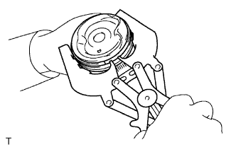
Disconnect the connecting rod from the piston.
Using a small screwdriver, pry off the snap ring from the piston.
 |
Gradually heat the piston to approximately 80 to 90°C (176 to 194°F).
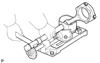 |
Using a brass bar and plastic-faced hammer, lightly tap out the piston pin and remove the connecting rod.
| 46. REMOVE CRANKSHAFT |
 |
Uniformly loosen the 10 bearing cap bolts in several passes in the sequence shown in the illustration.
Lift out the crankshaft.
Remove the upper bearings and upper thrust washers from the cylinder block.
| 47. REMOVE CYLINDER BLOCK WATER DRAIN COCK |
| 48. REMOVE OIL NOZZLE |
Using a 5 mm hexagon wrench, remove the oil nozzle.
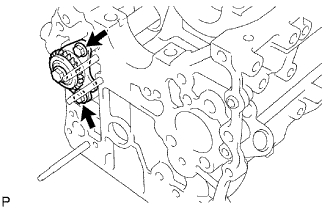
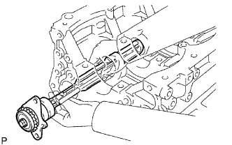
| 49. REMOVE NO. 1 BALANCE SHAFT |
 |
Remove the bolt.
 |
Remove the balance shaft from the cylinder block.
| 50. REMOVE NO. 1 BALANCE SHAFT DRIVEN GEAR |
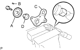 |
Mount the head portion of the balance shaft in a vise.
Remove the bolt.
Remove the No. 1 balance shaft driven gear (A), sliding key (B), No. 1 balance shaft thrust washer (C) and balance shaft thrust spacer (D).
| 51. REMOVE NO. 2 BALANCE SHAFT |
 |
Remove the 2 bolts.
 |
Remove the balance shaft from the cylinder block.
| 52. REMOVE NO. 2 BALANCE SHAFT DRIVEN GEAR |
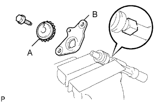 |
Mount the head portion of the balance shaft in a vise.
Remove the bolt.
Remove the No. 2 balance shaft driven gear (A) and No. 2 balance shaft thrust washer (B).
