ENGINE UNIT > INSPECTION |
| 1. INSPECT OIL NOZZLE |
Check the oil nozzle for damage or clogging.
If necessary, replace the oil nozzle.
| 1. INSPECT CHAIN |
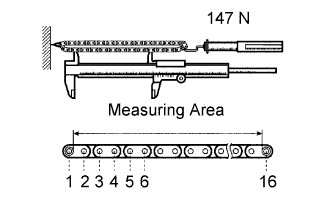 |
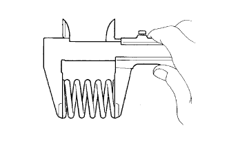
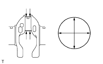
Pull the chain with a force of 147 N (15 kgf, 33 lbf) as shown in the illustration.
Using a vernier caliper, measure the length of 16 links.
| 2. INSPECT CAMSHAFT |
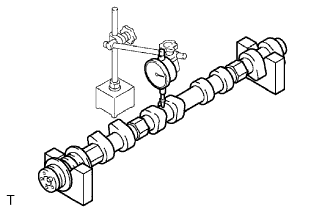 |
Check the camshaft for runout.
Place the camshaft on V-blocks.
Using a dial indicator, measure the circle runout at the center journal.
 |
Using a micrometer, measure the cam lobe height.
 |
Using a micrometer, measure the journal diameter.
| Journal | Diameter |
| No. 1 journal | 35.949 to 35.965 mm (1.4153 to 1.4159 in.) |
| Other journal | 26.959 to 26.975 mm (1.0614 to 1.0620 in.) |
| 3. INSPECT NO.2 CAMSHAFT |
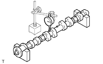 |
Check the camshaft for runout.
Place the camshaft on V-blocks.
Using a dial indicator, measure the circle runout at the center journal.
 |
Using a micrometer, measure the cam lobe height.
|
Using a micrometer, measure the journal diameter.
| Journal | Diameter |
| No. 1 journal | 35.949 to 35.965 mm (1.4153 to 1.4159 in.) |
| Other journal | 26.959 to 26.975 mm (1.0614 to 1.0620 in.) |
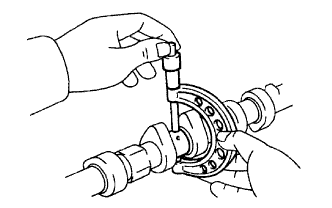
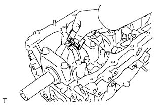
| 4. INSPECT CAMSHAFT TIMING GEAR (VVT CONTROLLER OPERATION) |
 |
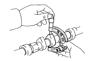
Check the lock of the camshaft timing gear.
Clamp the camshaft in a vise, and confirm that the camshaft timing gear is locked.
Release the lock pin.
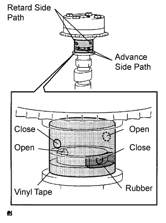
Cover the 4 oil paths of the cam journal with vinyl tape as shown in the illustration.
Break through the tape of the advance side path and the retard side path on the opposite side of the groove.
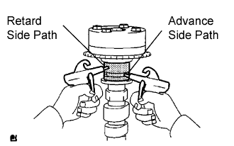 |
Apply approximately 200 kPa (2.0 kgf/cm2, 28 psi) of air pressure to the paths whose tape was broken in the procedure above.
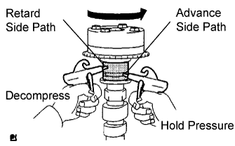 |
Check that the camshaft timing gear revolves in the advance direction when weakening the air pressure of the retard side path.
When the camshaft timing gear reaches the extreme advance position, remove the air gun from the retard side path and advance side path, in that order.
Check for smooth rotation.
Rotate the camshaft timing gear within its movable range several times, but do not turn it to the extreme retard position. Check that the gear rotates smoothly.
Check the lock in the extreme retard position.
Confirm that the camshaft timing gear is locked at the extreme retard position.
| 5. INSPECT CHAIN TENSIONER |
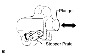 |
Move the stopper plate upward to release the lock. Push the plunger and check that it moves smoothly.
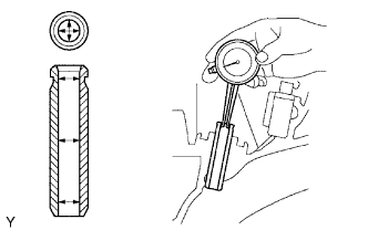
| 6. INSPECT CAMSHAFT TIMING SPROCKET |
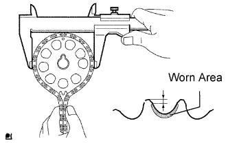 |
Measure the distance between the most worn out sprocket tip and the beginning of the worn area below the tip.
Wrap the chain around the sprocket.
Using a vernier caliper, measure the sprocket diameter with the chain.
| 7. INSPECT CAMSHAFT TIMING GEAR |
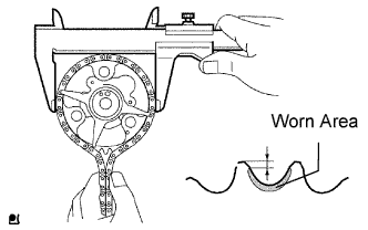 |
Measure the distance between the most worn out timing gear tip and the beginning of the worn area below the tip.
Wrap the chain around the timing gear.
Using a vernier caliper, measure the sprocket diameter with the chain.
| 8. INSPECT CRANKSHAFT TIMING SPROCKET |
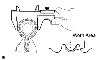 |
Measure the distance between the most worn out sprocket tip and the beginning of the worn area below the tip.
Wrap the chain around the drive sprocket.
Using a vernier caliper, measure the sprocket diameter with the chain.
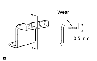
| 9. INSPECT CHAIN TENSIONER SLIPPER |
 |
Using a vernier caliper, measure the tensioner slipper wear.
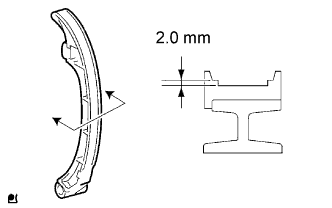
| 10. INSPECT CHAIN VIBRATION DAMPER |
 |
Using a vernier caliper, measure the vibration damper wear.
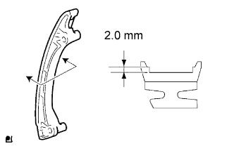
| 11. INSPECT TIMING CHAIN GUIDE |
 |
Using a vernier caliper, measure the chain guide wear.
| 12. INSPECT CYLINDER HEAD SET BOLT |
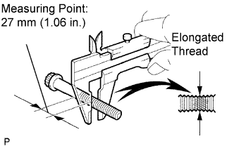
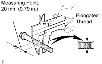 |
Using a vernier caliper, measure the minimum diameter of the elongated thread at the measuring point.
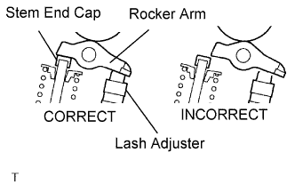
| 13. INSPECT VALVE LASH ADJUSTER |
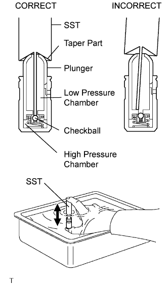 |
Place the lash adjuster into a container full of engine oil.
Insert SST's tip into the lash adjuster's plunger and use the tip to press down on the checkball inside the plunger.
Squeeze the SST and lash adjuster together to move the plunger up and down 5 to 6 times.
Check the movement of the plunger and bleed air.
After bleeding air, remove SST. Then, try to quickly and firmly press the plunger with a finger.
| 14. INSPECT CYLINDER HEAD FOR FLATNESS |
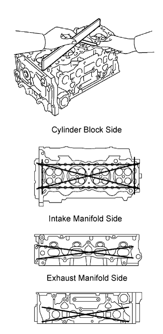 |
Using a precision straightedge and feeler gauge, measure the surface contacting the cylinder block and manifold for warpage.
| 15. INSPECT CYLINDER HEAD FOR CRACKS |
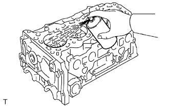 |
Using a dye penetrant, check the intake ports, exhaust ports and cylinder surface for cracks.
If cracked, replace the cylinder head.
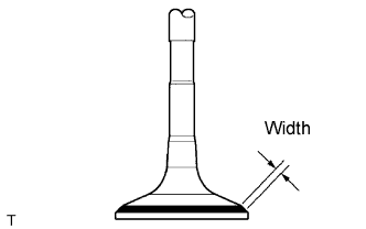
| 16. INSPECT INTAKE VALVE SEAT |
 |
Apply a light coat of Prussian blue (or white lead) to the valve face.
Lightly press the valve face against the valve seat.
Check the valve face and valve seat according to the following procedure.
If blue appears 360° around the valve face, the valve face is concentric. If not, replace the valve.
If blue appears 360° around the valve seat, the guide and valve face are concentric. If not, resurface the valve seat.
Check that the valve seat contact is in the middle of the valve face with the width between 1.0 to 1.4 mm (0.039 to 0.055 in.).
| 17. INSPECT EXHAUST VALVE SEAT |
 |
Apply a light coat of Pprussian blue (or white lead) to the valve face.
Lightly press the valve face against the valve seat.
Check the valve face and valve seat according to the following procedure.
If blue appears 360° around the valve face, the valve face is concentric. If not, replace the valve.
If blue appears 360° around the valve seat, the guide and valve face are concentric. If not, resurface the valve seat.
Check that the valve seat contact is in the middle of the valve face with the width between 1.0 to 1.4 mm (0.039 to 0.055 in.).
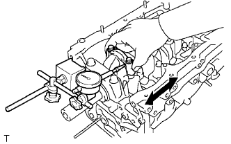
| 18. INSPECT CAMSHAFT THRUST CLEARANCE |
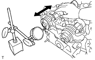 |
Using a dial indicator, measure the thrust clearance while moving the camshaft back and forth.
| 19. INSPECT CAMSHAFT OIL CLEARANCE |
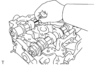 |
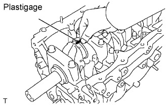
Clean the bearing caps and camshaft journals.
Place the camshafts on the cylinder head.
Lay a strip of Plastigage across each of the camshaft journals.
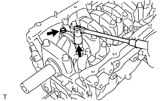
Install the bearing caps.
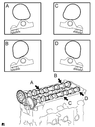  |
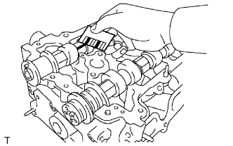
Set the camshaft and No. 2 camshaft as shown in the illustration.
 |
Loosely install the No. 1 camshaft bearing cap.
Check the proper location of each No. 2 camshaft bearing cap and install each one.
Install a new O-ring to the camshaft bearing cap No. 1.
Loosely install the oil delivery pipe.
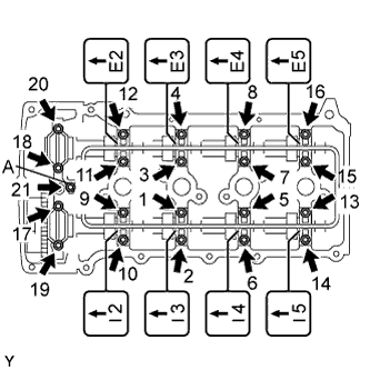
Tighten the 21 bolts in the order shown in the illustration.
Remove the bearing caps.
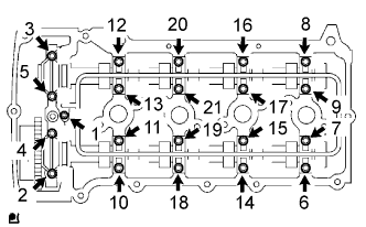 |
Uniformly loosen and remove the 21 bearing cap bolts on the camshafts in the sequence shown in the illustration. Then remove the oil delivery pipe, O-ring and 9 bearing caps.
Remove the 2 camshafts.
 |
Measure the plastigage at its widest point.
| Journal | Oil clearance |
| No. 1 journal | 0.035 to 0.072 mm (0.0014 to 0.0029 in.) |
| Other journal | 0.025 to 0.062 mm (0.0010 to 0.0028 in.) |
Completely remove the Plastigage.
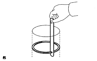
| 20. INSPECT INNER COMPRESSION SPRING |
 |
Using a vernier caliper, measure the free length of the inner compression spring.
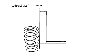 |
Using a steel square, measure the deviation of the inner compression spring.
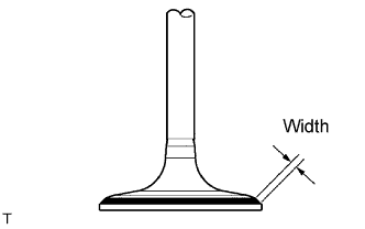
| 21. INSPECT INTAKE VALVE |
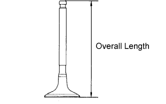 |
Using a vernier caliper, measure the valve's overall length.
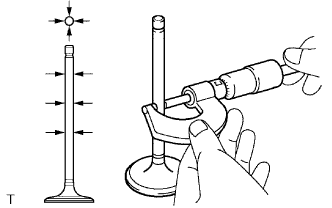 |
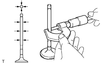
Using a micrometer, measure the diameter of the valve stem.
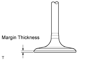 |
Using a vernier caliper, measure the valve head margin thickness.
| 22. INSPECT EXHAUST VALVE |
|
Using a vernier caliper, measure the valve's overall length.
 |
Using a micrometer, measure the diameter of the valve stem.
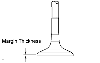 |
Using a vernier caliper, measure the valve head margin thickness.
| 23. INSPECT INTAKE VALVE GUIDE BUSH |
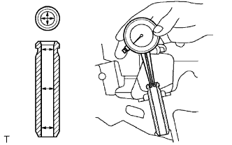 |
Using a caliper gauge, measure the inside diameter of the guide bush.
Subtract the valve stem diameter measurement from the guide bush inside diameter measurement.
| 24. INSPECT EXHAUST VALVE GUIDE BUSH |
 |
Using a caliper gauge, measure the inside diameter of the guide bush.
Subtract the valve stem diameter measurement from the guide bush inside diameter measurement.
| 25. INSPECT CONNECTING ROD THRUST CLEARANCE |
 |
Using a dial indicator, measure the thrust clearance while moving the connecting rod back and forth.
| 26. INSPECT CONNECTING ROD OIL CLEARANCE |
Check that the matchmarks on the connecting rod and cap are aligned to ensure the correct reassembly.
 |
Remove the 2 connecting rod cap bolts.
Using the 2 removed connecting rod cap bolts, remove the connecting rod cap and lower bearing by wiggling the connecting rod cap right and left.
Clean the crank pin and bearing.
Check the crank pin and bearing for pitting and scratches.
 |
Lay a strip of Plastigage on the crank pin.
|
Install the connecting rod cap (see reassembly procedure).
Remove the 2 bolts and connecting rod cap.
 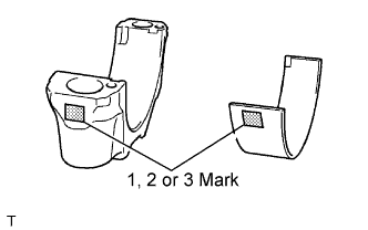 |
Measure the Plastigage at its widest point.
| Mark | Thickness |
| 1 | 1.484 to 1.487 mm (0.0584 to 0.0585 in.) |
| 2 | 1.488 to 1.490 mm (0.0586 to 0.0587 in.) |
| 3 | 1.491 to 1.493 mm (0.0587 to 0.0588 in.) |
Completely remove the Plastigage.
| 27. INSPECT CRANKSHAFT THRUST CLEARANCE |
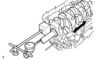 |
Using a dial indicator, measure the thrust clearance while prying the crankshaft back and forth with a screwdriver.
| 28. INSPECT CRANKSHAFT OIL CLEARANCE |
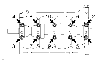 |
Uniformly loosen the 10 bearing cap bolts in several passes in the sequence shown in the illustration.
Lift out the crankshaft.
Clean each main journal and bearing.
Check each main journal and bearing for pitting and scratches.
If the journal or bearing is damaged, replace the bearings. If necessary, grind or replace the crankshaft.
Place the crankshaft on the cylinder block.
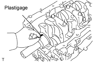 |
Lay a strip of Plastigage across each journal.
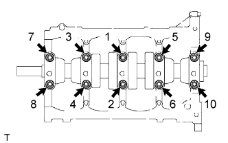 |
Install the 5 crankshaft bearing caps with the 10 bolts (see reassembly procedure).
Remove the 10 bolts and 5 crankshaft bearing caps (see removal steps).
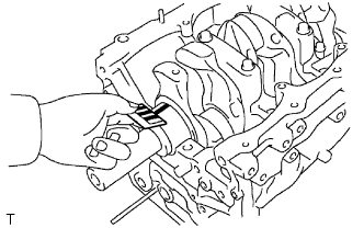  |
Measure the Plastigage at its widest point.
| Journal | Oil clearance |
| No. 3 | 0.030 to 0.055 mm (0.0012 to 0.0022 in.) |
| Except No. 3 | 0.024 to 0.049 mm (0.0009 to 0.0019 in.) |
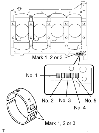
| Mark | Diameter |
| 1 | 64.004 to 64.010 mm (2.5198 to 2.5201 in.) |
| 2 | 64.010 to 64.016 mm (2.5201 to 2.5203 in.) |
| 3 | 64.016 to 64.022 mm (2.5203 to 2.5206 in.) |
| Mark | Diameter |
| 1 | 1.987 to 1.990 mm (0.0782 to 0.0783 in.) |
| 2 | 1.990 to 1.993 mm (0.0783 to 0.0785 in.) |
| 3 | 1.993 to 1.996 mm (0.0785 to 0.0786 in.) |
Completely remove the Plastigage.
| 29. INSPECT CYLINDER BLOCK |
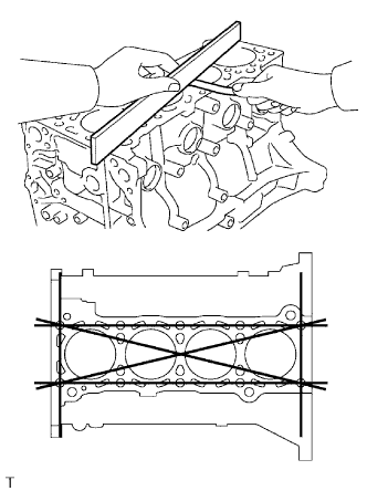 |
Inspect for flatness.
Using a precision straightedge and feeler gauge, measure the surface contacting the cylinder head gasket for warpage.
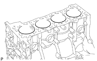 |
Visually check the cylinder for vertical scratches.
If deep scratches are present, rebore all the 4 cylinders. If necessary, replace the cylinder block.
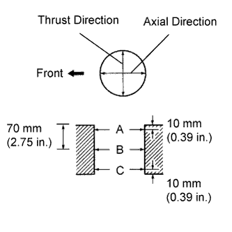 |
Inspect the cylinder bore diameter.
Using a cylinder gauge, measure the cylinder bore diameter at positions A, B and C in the thrust and axial directions.
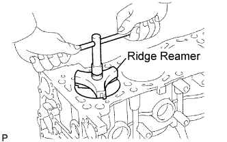 |
Inspect the cylinder ridge.
If the wear is less than 0.2 mm (0.008 in.), using a ridge reamer, grind the top of the cylinder.
| 30. INSPECT PISTON WITH PIN |
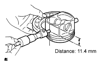 |
Inspect the piston oil clearance.
Using a micrometer, measure the piston diameter at right angles to the piston center line, the indicated distance from the piston end.
| Piston | Diameter |
| Standard | 85.951 to 85.986 mm (3.3839 to 3.3853 in.) |
| O/S 0.50 | 86.431 to 86.486 mm (3.4028 to 3.4050 in.) |
Measure the cylinder bore diameter in the thrust directions.
Subtract the piston diameter measurement from the cylinder bore diameter measurement.
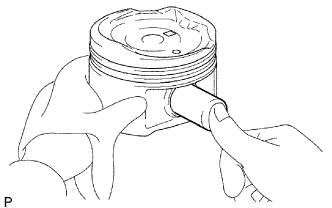 |
Inspect the piston pin fit.
At 60°C (140°F), check that the position pin can be pushed into the piston hole with your thumb.
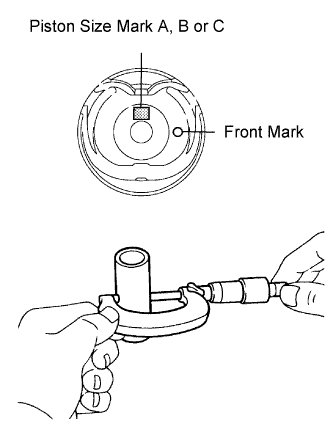 |
Inspect the piston pin diameter.
Using a micrometer, measure the piston pin diameter.
| Size Mark | Diameter |
| A | 21.997 to 22.000 mm (0.86602 to 0.86614 in.) |
| B | 22.001 to 22.003 mm (0.86615 to 0.86626 in.) |
| C | 22.003 to 22.006 mm (0.86627 to 0.86638 in.) |
| 31. INSPECT PISTON RING SET |
 |
Using a feeler gauge, measure the clearance between a new piston ring and the wall of the ring groove.
| Ring | Groove clearance |
| No. 1 | 0.020 to 0.075 mm (0.0008 to 0.0030 in.) |
| No. 2 | 0.020 to 0.065 mm (0.0008 to 0.0026 in.) |
| Oil | 0.020 to 0.070 mm (0.0008 to 0.0028 in.) |
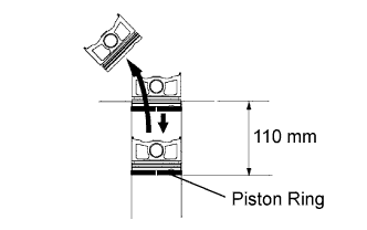 |
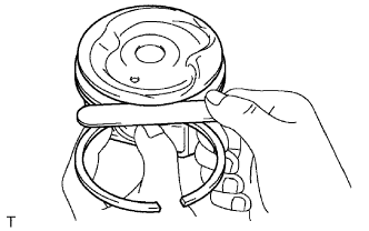
Inspect the piston ring end gap.
Insert the piston ring into the cylinder bore.
Using a piston, push the piston ring a little beyond the bottom of the ring travel, 110 mm (4.33 in.) from the top of the cylinder block.
 |
Using a feeler gauge, measure the end gap.
| Ring | Standard end gap |
| No. 1 | 0.22 to 0.34 mm (0.0087 to 0.0134 in.) |
| No. 2 | 0.45 to 0.57 mm (0.0177 to 0.0224 in.) |
| Oil | 0.10 to 0.40 mm (0.0039 to 0.0157 in.) |
| Ring | Maximum end gap |
| No. 1 | 0.90 mm (0.0354 in.) |
| No. 2 | 1.36 mm (0.0535 in.) |
| Oil | 0.75 mm (0.0295 in.) |
| 32. INSPECT CONNECTING ROD |
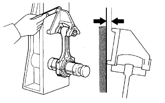 |
Using a rod aligner and feeler gauge, check the connecting rod alignment.
Check for bend.
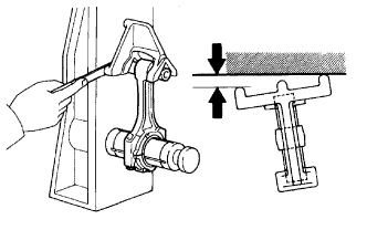 |
Check for twist.
| 33. INSPECT PISTON PIN OIL CLEARANCE |
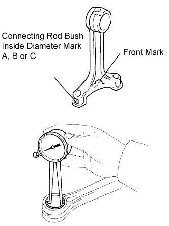 |
Inspect the piston pin oil clearance.
Using a caliper gauge, measure the inside diameter of the connecting rod bush.
| Size Mark | Diameter |
| A | 22.005 to 22.008 mm (0.86633 to 0.86645 in.) |
| B | 22.008 to 22.011 mm (0.86645 to 0.86657 in.) |
| C | 22.011 to 22.014 mm (0.86657 to 0.86669 in.) |
Subtract the piston pin diameter measurement from the bush inside diameter measurement.
| 34. INSPECT CONNECTING ROD BOLT |
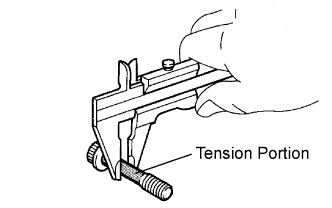 |
Using a vernier caliper, measure the tension portion diameter of the bolt.
| 35. INSPECT CRANKSHAFT |
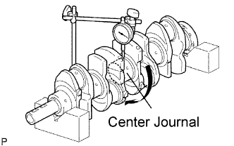 |
Inspect for circle runout.
Place the crankshaft on V-blocks.
Using a dial indicator, measure the circle runout at the center journal.
 |
Inspect the main journals.
Using a micrometer, measure the diameter of each main journal.
| Journal | Diameter |
| No. 3 | 59.981 to 59.994 mm (2.3615 to 2.3620 in.) |
| Except No. 3 | 59.987 to 60.000 mm (2.3229 to 2.3622 in.) |
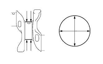
Check each main journal for taper and out-of-round as shown in the illustration.
 |
Inspect the crank pin.
Using a micrometer, measure the diameter of each crank pin.
Check each crank pin for taper and out-of-round as shown in the illustration.
| 36. INSPECT CRANKSHAFT BEARING CAP SET BOLT |
 |
Using a vernier caliper, measure the minimum diameter of the elongated thread at the measuring point.
