ENGINE UNIT > REPLACEMENT |
| 1. REMOVE TIMING CHAIN COVER OIL SEAL |
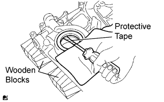 |
Using a screwdriver with its tip taped, pry out the oil seal.
| 2. INSTALL TIMING CHAIN COVER OIL SEAL |
 |
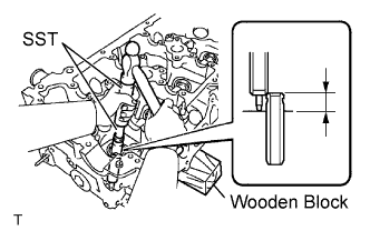
Place the timing chain cover on wooden blocks.
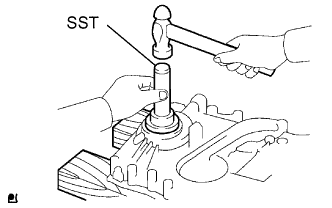
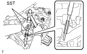
Using SST, tap in the oil seal until its surface is flush with the timing gear case edge.
Apply a light coat of MP grease to a new oil seal lip.
| 3. REMOVE ENGINE REAR OIL SEAL |
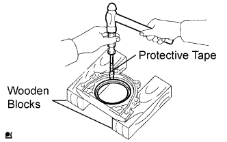 |
Place the oil seal retainer on wooden blocks.
Using a screwdriver with its tip taped and a hammer, tap out the oil seal.
| 4. INSTALL ENGINE REAR OIL SEAL |
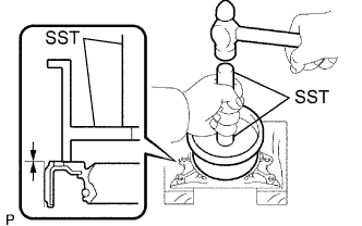 |
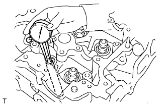
Place the oil seal retainer on wooden blocks.
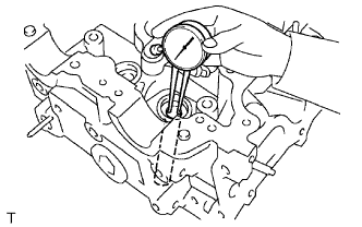
Using SST, tap in the oil seal until its surface is flush with the oil seal retainer edge.
| 5. REMOVE INTAKE VALVE GUIDE BUSH |
 |
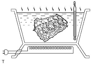
Heat the cylinder head to 80 to 100°C (176 to 212°F).
 |
Place the cylinder head on wooden blocks.
Using SST and a hammer, tap out the guide bush.
| 6. INSTALL INTAKE VALVE GUIDE BUSH |
 |
Using a caliper gauge, measure the bush bore diameter of the cylinder head.
Select a new guide bush (STD or O/S 0.05).
| Bush Bore Diameter | Bush Size |
| 10.285 to 10.306 mm (0.4049 to 0.4057 in.) | Use STD |
| 10.335 to 10.356 mm (0.4069 to 0.4077 in.) | Use O/S 0.05 |
|
Heat the cylinder head to 80 to 100°C (176 to 212°F).
 |
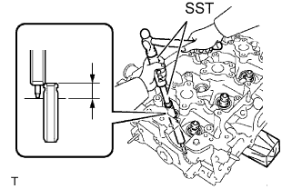
Place the cylinder head on wooden blocks.
Using SST, tap in a new valve guide bush to the specified protrusion height.
Using a sharp 5.5 mm reamer, ream the valve guide bush to obtain the standard specified clearance.
| 7. REMOVE EXHAUST VALVE GUIDE BUSH |
 |
Heat the cylinder head to 80 to 100°C (176 to 212°F).
Place the cylinder head on wooden blocks.
Using SST and a hammer, tap out the guide bush.
| 8. INSTALL EXHAUST VALVE GUIDE BUSH |
 |
Using a caliper gauge, measure the bush bore diameter of the cylinder head.
Select a new guide bush (STD or O/S 0.05).
| Bush Bore Diameter | Bush Size |
| 10.285 to 10.306 mm (0.4049 to 0.4057 in.) | Use STD |
| 10.335 to 10.356 mm (0.4069 to 0.4077 in.) | Use O/S 0.05 |
 |
Heat the cylinder head to 80 to 100°C (176 to 212°F).
 |
Place the cylinder head on the wooden blocks.
Using SST, tap in a new valve guide bush to the specified protrusion height.
Using a sharp 5.5 mm reamer, ream the valve guide bush to obtain the standard specified clearance.
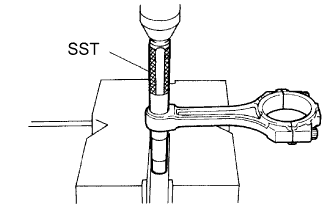
| 9. REMOVE CONNECTING ROD SMALL END BUSH |
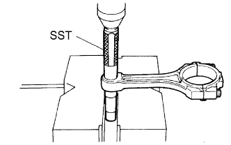 |
Using SST and a press, press out the bush.
| 10. INSTALL CONNECTING ROD SMALL END BUSH |
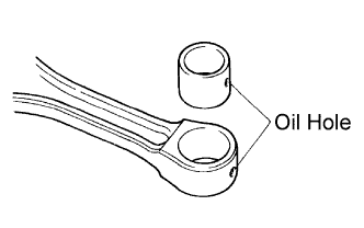 |
Align the oil holes of a new bush and the connecting rod.
 |
Using SST and a press, press in the bush.
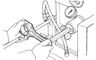 |
Using a pin hole grinder, hone the bush to obtain the standard specified clearance between the bush and piston pin.
Check that the piston pin fits at normal room temperature.
Coat the piston pin with engine oil, and push it into the connecting rod with your thumb.
