ENGINE UNIT > REASSEMBLY |
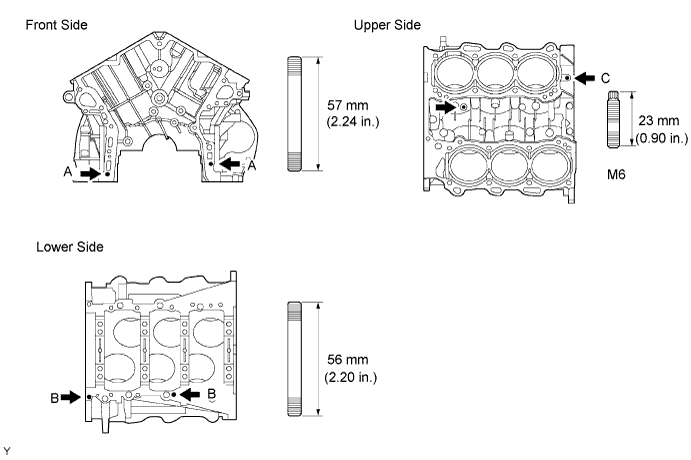
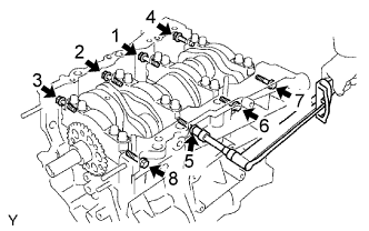
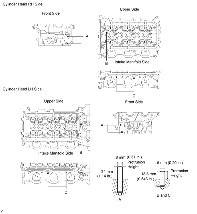
| 1. INSTALL STUD BOLT |
Install the stud bolts as shown in the illustration.
| 2. INSTALL STRAIGHT PIN |
Using a plastic-faced hammer, tap into the straight pin.
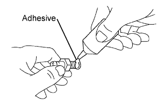
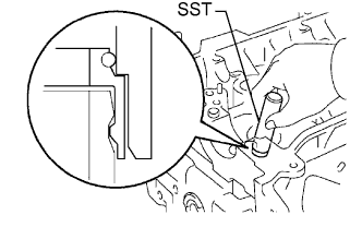
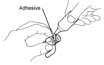
| 3. INSTALL TIGHT PLUG |
Apply adhesive around tight plugs.
Using SST, tap in the tight plugs as shown in the illustration.
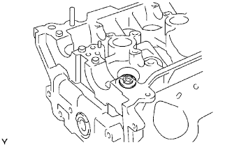
| 4. INSTALL OIL JET |
 |
Using a screwdriver and hammer, tap in a oil jet.
| 5. INSTALL OIL NOZZLE |
 |
Using a 5 mm socket hexagon wrench, install the 3 oil nozzles.
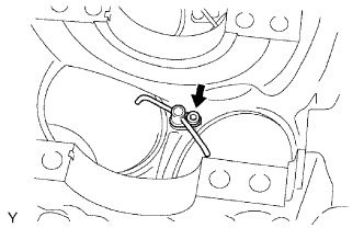
| 6. INSTALL PISTON PIN HOLE SNAP RING |
 |
Using a small screwdriver, install a new snap ring at one end of the piston pin hole.
| 7. INSTALL PISTON |
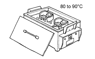 |
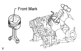
Gradually heat the piston to about 80°C (176°F).
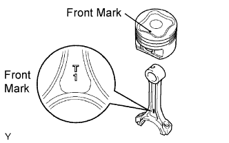 |
Coat the piston pin with engine oil.
Align the front marks of the piston and connecting rod, and push in the piston pin with thumb.
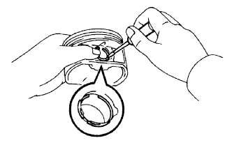
| 8. INSTALL PISTON PIN HOLE SNAP RING |
|
Using a small screwdriver, install a new snap ring on the other end of the piston pin hole.
| 9. INSTALL PISTON RING SET |
 |
Install the oil ring expander and 2 side rails by hand.
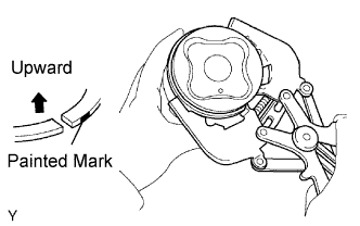
Using a piston ring expander, install the 2 compression rings.
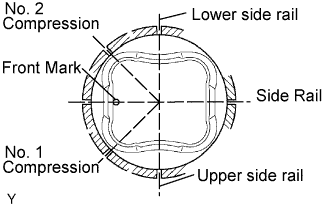 |
Position the piston rings so that the ring ends are as shown.
| 10. INSTALL CONNECTING ROD BEARING |
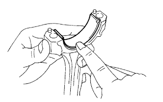 |
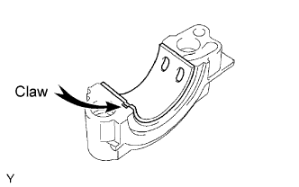
Align the bearing claw with the groove of the connecting rod or connecting cap.
| 11. INSTALL CRANKSHAFT BEARING |
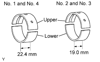 |
Clean each main journal and bearing.
 |
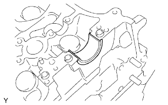
Align the bearing claw with the claw groove of the cylinder block, and push in the 4 upper bearings.
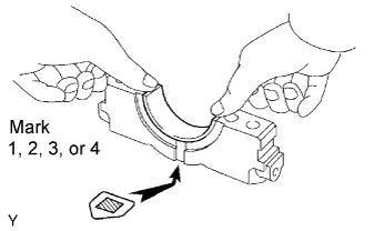 |
Align the bearing claw with the claw groove of the main bearing cap, and push in the 4 lower bearings.
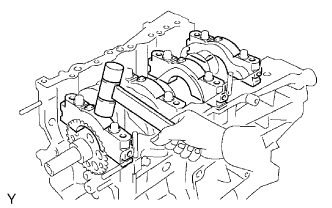
| 12. INSTALL CRANKSHAFT |
Apply engine oil to upper bearing and install the crankshaft on the cylinder block.
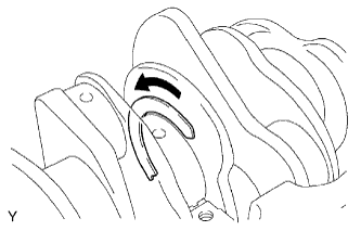 |
Install the 2 upper thrust washers to the No. 2 journal position of the cylinder block.
Push the crankshaft toward the front (rear) side.
Install the 2 upper thrust washers with the oil grooves facing outward.
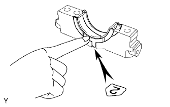 |
Install the 2 lower thrust washers on the No. 2 bearing cap with the grooves facing outward.
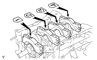 |
Examine the front marks and numbers and install the bearing caps on the cylinder block.
Apply a light coat of engine oil on the threads and under the head of bearing cap bolts.
Temporarily install the 8 main bearing cap bolts to the inside positions.
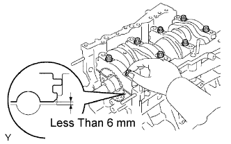 |
Insert the main bearing cap with hand until the clearance between the main bearing cap and the cylinder block will become less than 6mm (0.23 in.) by making the 2 internal bearing cap bolts as a guide.
 |
Using a plastic-faced hammer, lightly tap the bearing cap to ensure a proper fit.
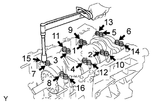 |
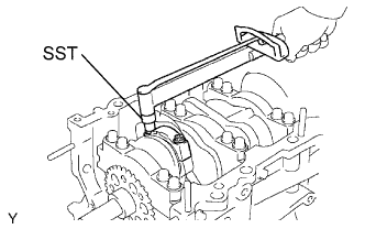
Apply a light coat of engine oil on the threads and under the head of main bearing cap bolts.
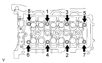
Install and uniformly tighten the 16 main bearing cap bolts in several passes, in the sequence shown.
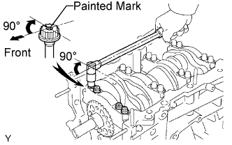 |
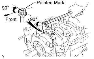
Mark the front side of the bearing cap bolts with paint.
Retighten the bearing cap bolts by 90°C in the sequence shown.
Check that the painted mark is now at a 90°angle to the front.
Check that the crankshaft turns smoothly.
 |
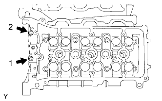
Install and uniformly tighten the 8 main bearing cap bolts in several passes, in the sequence shown.
| 13. INSTALL PISTON WITH CONNECTING ROD |
 |
Apply engine oil to the cylinder walls, the pistons, and the surfaces of connecting rod bearings.
Check the position of the piston ring ends.
Using a piston ring compressor, push the correctly numbered piston and connecting rod assemblies into each cylinder with the front mark of the piston facing forward.
Check that the protrusion of the connecting rod cap is facing in the correct direction.
Apply a light coat of engine oil on the threads and under the heads of the connecting rod cap bolts.
 |
Using SST, tighten the bolts in several passes by the specified torque.
 |
Mark the front side of the each connecting cap bolt with paint.
Retighten the cap bolts by 90° as shown.
Check that the crankshaft turns smoothly.
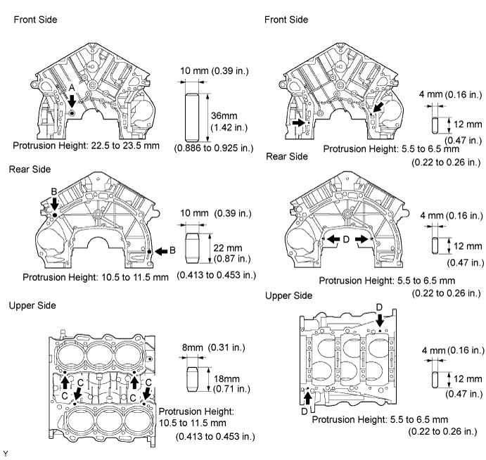
| 14. INSTALL RING PIN |
Using a plastic-faced hammer, tap in the new ring pins to the specified protrusion height.
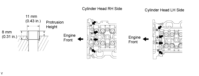
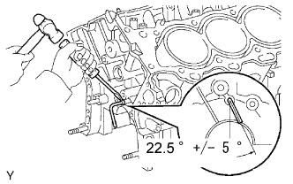
| 15. INSTALL STRAIGHT PIN |
Using a plastic-faced hammer, tap in the new straight pins to the specified protrusion height.
| Item | Specified Condition |
| A | 17.5 to 19.5 mm (0.689 to 0.768 in.) |
| B | 7.5 to 8.5 mm (0.295 to 0.335 in.) |
| C | 7.0 to 9.0 mm (0.276 to 0.354 in.) |
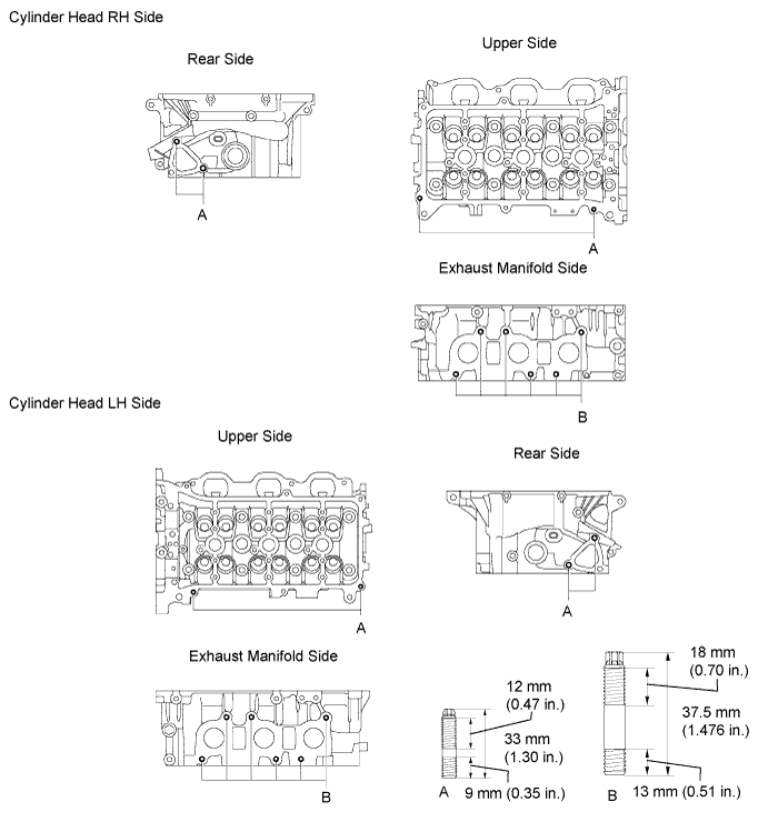
| 16. INSTALL STUD BOLT |
Using E5 and E7 "torx" socket wrench, install the stud bolts.
| 17. INSTALL UNION |
 |
Apply adhesive to 2 or 3 threads of the bolt end.
Using a 12 mm deep socket wrench, install the unions.
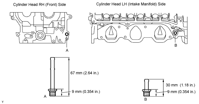
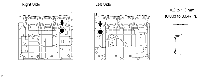
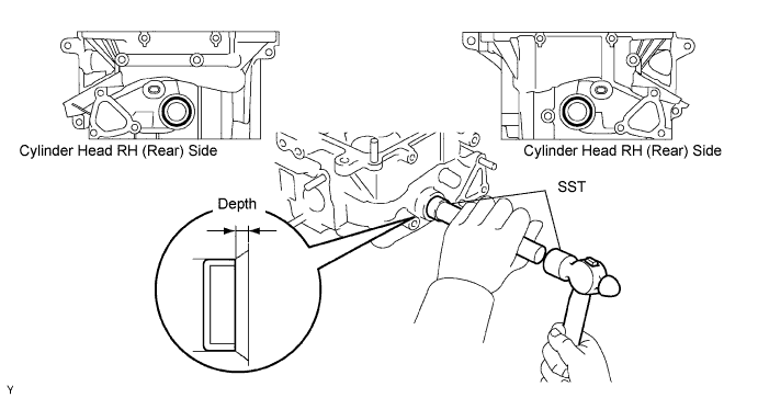
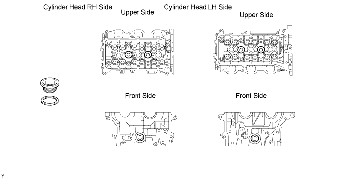
| 18. INSTALL TIGHT PLUG |
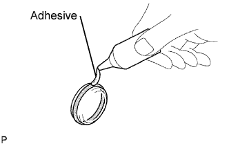 |
Apply adhesive around tight plug.
Using SST, tap in the tight plugs to the specified depth.
| 19. INSTALL WITH HEAD STRAIGHT SCREW PLUG |
Using a 16 mm hexagon wrench, install a new gasket and straight screw plug.
| 20. INSTALL VALVE STEM OIL SEAL |
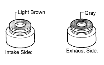 |
Apply a light coat of engine oil to the valve guide bush.
 |
Using SST, push in a new valve stem oil seal.
| 21. INSTALL VALVE SPRING SEAT |
 |
| 22. INSTALL VALVE |
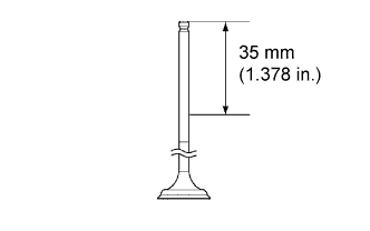 |
Apply the engine oil to the valve as shown in the illustration.
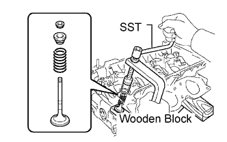 |
Place the cylinder head on the wooden block.
Install the valve, inner compression spring and valve spring retainer.
Using SST, compress the inner compression spring and place the 2 valve spring retainer locks around the valve stem.
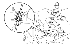 |
Using a 5 mm pin punch, lightly tap the valve stem tip to ensure a proper fit.
| 23. INSTALL VALVE LIFTER |
 |
Apply the engine oil to the valve stem end and valve lifter, and install its.
Check that the valve lifter rotates smoothly by hand.
| 24. INSTALL ENGINE REAR OIL SEAL RETAINER |
 |
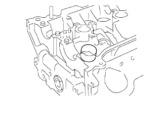
Remove any old packing (FIPG) material and be careful not to drop any oil on the contact surfaces of the oil seal retainer and cylinder block.
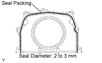
Apply a continuous line of the seal packing to the oil seal retainer as shown in the illustration.
Install the oil seal retainer with the 5 bolts and 2 nuts.
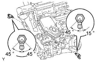
| 25. INSTALL KNOCK SENSOR |
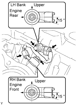 |
Install the 2 knock sensors with the 2 bolts as shown in the illustration.
Connect the knock sensor connectors.
| 26. INSTALL NO. 1 WATER OUTLET PIPE |
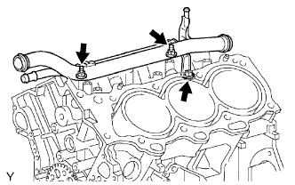 |
Install the water outlet pipe with the bolt and 2 nuts.
| 27. INSTALL CYLINDER HEAD GASKET |
Remove any old packing (FIPG) material and be careful not to drop any oil on the contact surfaces of the cylinder head and cylinder block.
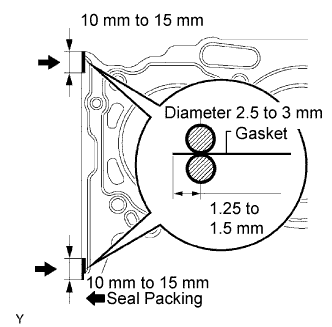 |
Apply a continuous line of the seal packing to a new cylinder head gasket as shown in the illustration.
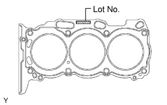 |
Place the cylinder head gasket on the cylinder block surface with the Lot No. stamp upward.
| 28. INSTALL CYLINDER HEAD |
Place the RH cylinder head on the cylinder head gasket.
Install the 8 cylinder head bolts.
Apply a light coat of engine oil on the threads and under the heads of the cylinder head bolts.
Install the plate washer to the cylinder head bolt.
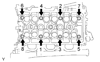 |
Using a 10 mm bi-hexagon wrench, temporarily tighten each bolts in the several passes, as the sequence shown in the illustration, and fully tighten with specified torque.
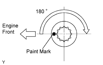 |
Mark the front side of each cylinder head bolt with paint.
Retighten the cylinder head bolts by 180° in the numerical order shown.
Check that the painted marks are now a 180° angle to the front.
| 29. INSTALL NO. 2 CYLINDER HEAD GASKET |
Remove any old packing (FIPG) material and be careful not to drop any oil on the contact surfaces of the cylinder head and cylinder block.
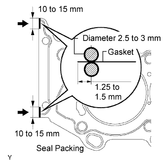 |
Apply a continuous line of the seal packing to a new cylinder head gasket as shown in the illustration.
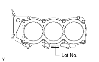 |
Place the cylinder head gasket on the cylinder block surface with the Lot No. stamp upward.
| 30. INSTALL CYLINDER HEAD LH |
Place the LH cylinder head on the cylinder head gasket.
Install the 8 cylinder head bolts.
Apply a light coat of engine oil on the threads and under the heads of the cylinder head bolts.
Install the plate washer to the cylinder head bolt.
 |
Using a 10 mm bi-hexagon wrench, temporarily tighten each bolts in the several passes, as the sequence shown in the illustration, and fully tighten with specified torque.
|
Mark the front side of each cylinder head bolt with paint.
Retighten the cylinder head bolts by 180°in the numerical order shown.
Check that the painted marks are now a 180° angle to the front.
 |
Install the 2 cylinder head bolts.
Apply a light coat of engine oil on the threads and under the heads of the cylinder head bolts.
Install and uniformly tighten the 2 cylinder head bolts, in several passes, in the sequence shown.
| 31. INSTALL NO. 1 CAMSHAFT BEARING |
 |
Align the bearing claw with the claw groove of the bearing cap, and push in the camshaft bearing.
| 32. INSTALL NO. 2 CAMSHAFT BEARING |
 |
Install the No. 2 camshaft bearing to the cylinder head.
| 33. INSTALL CAMSHAFT |
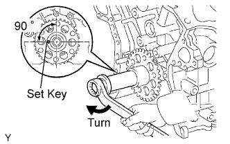 |
Set the crankshaft position.
Using the crankshaft pulley set bolt, turn the crankshaft, and set the crankshaft set key into the left horizontal position.
Apply new engine oil to the thrust portion and journal of the camshafts.
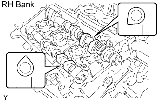 |
Install the camshaft of the RH bank.
Place the 2 camshafts onto the RH cylinder head with the cam lobes of No. 1 cylinder faced as shown in the illustration.
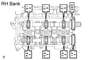 |
Install the 8 bearing caps in their proper locations.
Apply a light coat of engine oil on the threads and under the heads of the bearing cap bolts.
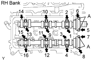 |
Install and uniformly tighten the 16 bearing cap bolts, in several passes, in the sequence shown.
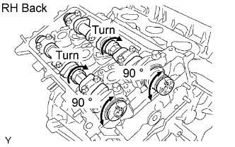 |
Rotate the camshafts clockwise using hexagonal portion of the each camshaft at 90° angle of the camshaft knock pin on the cylinder head.
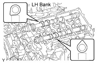 |
Install the camshafts of the LH bank.
Place the 2 camshafts onto the LH cylinder head with the cam lobes of No. 2 cylinder faced as shown in the illustration.
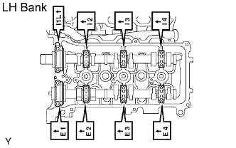 |
Install the 8 bearing caps in their proper locations.
Apply a light coat of engine oil on the threads and under the heads of the bearing cap bolts.
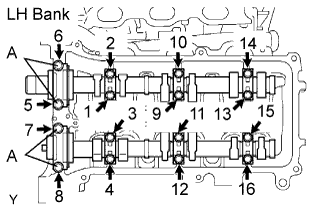 |
Install and uniformly tighten the 16 bearing cap bolts, in several passes, in the sequence shown.
| 34. INSTALL NO. 2 CHAIN TENSIONER |
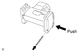 |
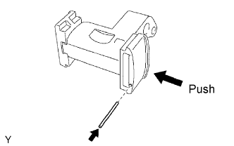
While pushing in the tensioner, insert a pin of diameter of 1.0 mm (0.039 in.) into the hole to fix it.
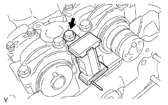 |
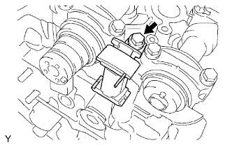
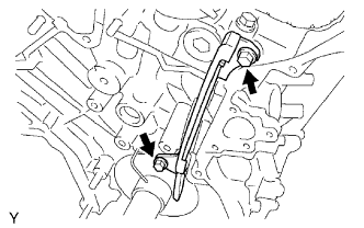
Install the No. 2 chain tensioner with the bolt.
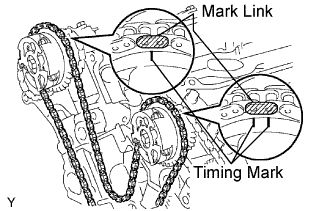
| 35. INSTALL CAMSHAFT TIMING GEARS AND NO. 2 CHAIN (RH BANK) |
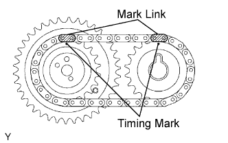 |
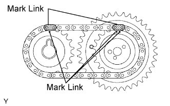
Align the mark links (yellow) with the timing marks (1 dot mark) of camshaft timing gears as shown in the illustration.
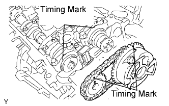 |
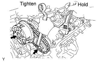
Align the timing marks on the camshaft timing gears with the timing marks on the bearing caps, and install the camshaft timing gears with the chain to the RH camshafts.
Temporarily install the 2 camshaft timing gear bolts.
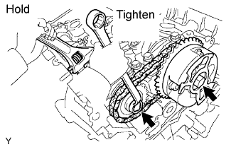 |
Hold the hexagonal portion of the camshaft with a wrench, and tighten the 2 bolts.
Remove the pin from the No. 2 chain tensioner.
| 36. INSTALL NO. 3 CHAIN TENSIONER |
 |
While pushing in the tensioner, insert a pin of diameter of 1.0 mm (0.039 in.) into the hole to hold it.
 |
Install the No. 3 chain tensioner with the bolt.
| 37. INSTALL CAMSHAFT TIMING GEARS AND NO. 2 CHAIN (LH BANK) |
 |
Align the mark links (yellow) with the timing marks (1 dot mark and 2 dot mark) of camshaft timing gears as shown in the illustration.
 |
Align the timing marks on the camshaft timing gears with the timing marks on the bearing caps, and install the camshaft timing gears with the chain to the LH camshafts.
Temporarily install the 2 camshaft timing gear bolts.
 |
Hold the hexagonal portion of the camshaft with a wrench, and tighten the 2 bolts.
Remove the pin from the No. 3 chain tensioner.
| 38. INSTALL NO. 1 CHAIN VIBRATION DAMPER |
 |
Install the No. 1 chain vibration damper with the 2 bolts.
| 39. INSTALL CAMSHAFT TIMING SPROCKET |
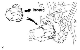 |
Align the timing gear set key with the key groove of the timing gear.
Install the timing gear onto the crankshaft, facing the gear side inward.
| 40. INSTALL CHAIN TENSIONER SLIPPER |
| 41. INSTALL NO. 1 CHAIN TENSIONER |
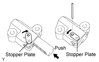 |
While rotating the stopper plate of the tensioner clockwise, push in the plunger of the tensioner as shown in the illustration.
While rotating the stopper plate of the tensioner counterclockwise, insert a bar of diameter of 3.5 mm (0.138 in.) into the holes in the stopper plate and tensioner to fix the stopper plate.
Install the chain tensioner with the 2 bolts.
| 42. INSTALL CHAIN |
 |
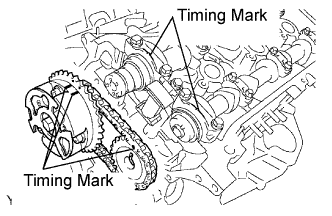
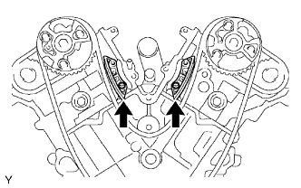
Set the No. 1 cylinder to TDC/compression.
Align the timing marks of the camshaft timing gears and bearing caps.
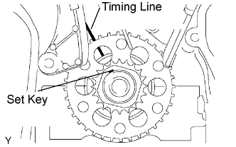 |
Using the crankshaft pulley set bolt, turn the crankshaft to align the crankshaft set key with the timing line of the cylinder block.
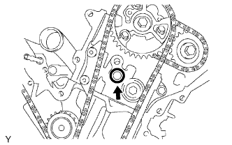
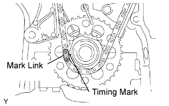 |
Align the mark link (yellow) with the timing mark of the crankshaft timing gear.
 |
Align the mark links (orange) with the timing marks of the camshaft timing gears, and install the chain.
| 43. INSTALL NO .2 CHAIN VIBRATION DAMPER |
 |
Install the 2 No. 2 chain vibration dampers.
| 44. INSTALL NO. 1 IDLE GEAR |
Apply a light coat of engine oil to rotating surface of the No. 1 idle gear shaft.
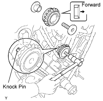 |
Temporarily install the No. 1 idle gear shaft and idle gear with the No. 2 idle gear shaft while aligning the knock pin of the No. 1 idle gear shaft with the knock pin groove of the cylinder block.
Using a 10 mm hexagon wrench, tighten the No. 2 idle gear shaft.
Remove the bar from the chain tensioner.
| 45. INSTALL TIMING CHAIN COVER |
Remove any old packing (FIPG) material and be careful not to drop any oil on the contact surfaces of the timing chain cover, cylinder head and cylinder block.
 |
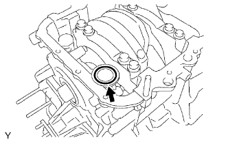
Install a new O-ring to the LH cylinder head as shown in the illustration.
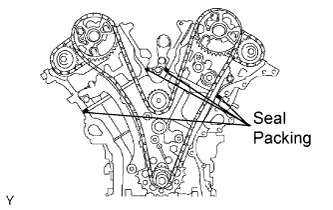 |
Apply a continuous bead of the seal packing to 4 locations as shown in the illustration.
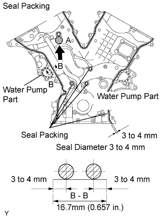 |
Apply a continuous bead of the seal packing to the timing chain cover as shown in the illustration.
 |
Engage the spline teeth of the oil pump drive rotor with the large teeth of the crankshaft timing gear, and slide the timing chain cover.
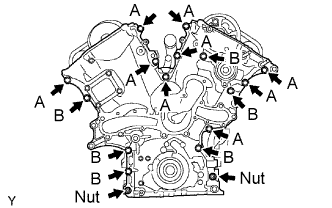 |
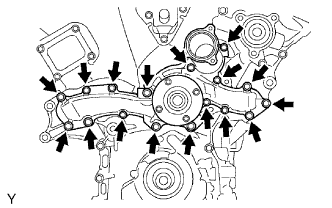
Install the timing chain cover with the 15 bolts and 2 nuts. Uniformly tighten the bolts and nuts in several passes.
| 46. INSTALL WATER PUMP |
 |
Install a new gasket and the water pump with the 17 bolts.
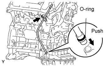
| 47. INSTALL NO. 1 OIL PAN |
Remove any old packing (FIPG) material and be careful not to drop any oil on the contact surfaces of the cylinder block, rear oil seal retainer and oil pan.
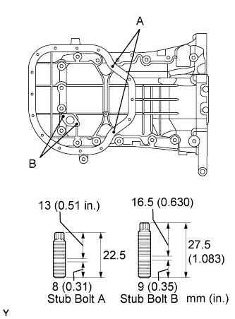 |
Install the 4 stud bolts.
 |
Install a new O-ring to the oil pump.
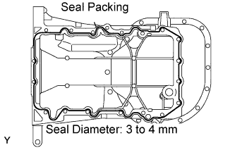 |
Apply a continuous line of the seal packing to the oil pan as shown in the illustration.
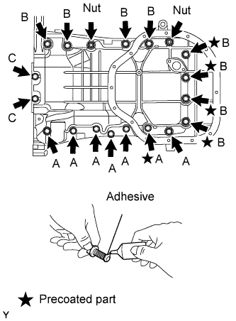 |
Install the oil pan with the 17 bolts and 2 nuts. Uniformly tighten the bolts and nuts in several passes.
| 48. INSTALL OIL STRAINER |
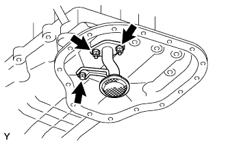 |
Install a new gasket and the oil strainer with the 2 nuts.
| 49. INSTALL NO. 2 OIL PAN |
Remove any old packing (FIPG) material and be careful not to drop any oil on the contact surfaces of the No. 2 oil pan and oil pan.
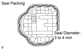 |
Apply a continuous line of the seal packing as shown in the illustration.
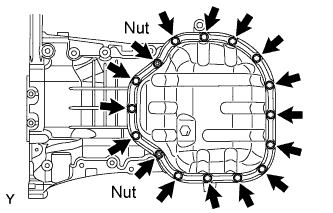 |
Install the No. 2 oil pan with the 10 bolts and 2 nuts. Uniformly tighten the bolts and nuts in several passes.
| 50. INSTALL OIL PAN DRAIN PLUG |
Install the drain plug with a new gasket.
| 51. INSTALL CRANKSHAFT PULLEY |
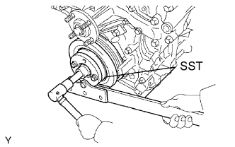 |
Using SST, install the pulley set bolt.
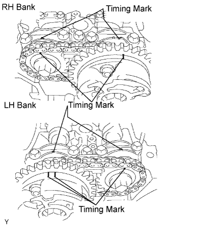
| 52. SET NO. 1 CYLINDER TO TDC/COMPRESSION |
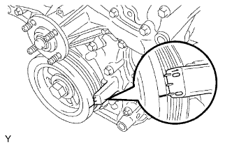 |
Turn the crankshaft pulley, and align its groove with the timing mark "0" of the timing chain cover.
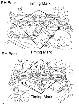 |
Check that the timing marks of the camshaft timing gears are aligned with the timing marks of the bearing cap as shown in the illustration.
If not, turn the crankshaft 1 revolution (360°) and align the timing marks as above.
| 53. INSPECT VALVE CLEARANCE |
| 54. INSTALL CYLINDER HEAD COVER RH |
Remove any old packing (FIPG) material and be careful not to drop any oil on the contact surfaces of the cylinder head, timing chain cover and cylinder head cover.
Install the gasket to the cylinder head cover.
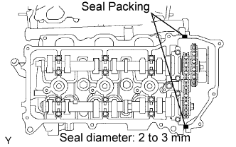 |
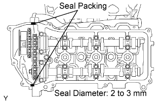
Apply a continuous bead of the seal packing to the cylinder head and timing chain cover as shown in the illustration.
Install the seal washers to the bolts.
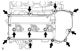 |
Install the cylinder head cover with the 10 bolts and 2 nuts. Uniformly tighten the bolts and nuts in several passes.
| 55. INSTALL CYLINDER HEAD COVER LH |
Remove any old packing (FIPG) material and be careful not to drop any oil on the contact surfaces of the cylinder head, timing chain cover and cylinder head cover.
Apply adhesive on the threads of the ventilation valve.
Install the ventilation valve to the cylinder head cover.
Install the gasket to the cylinder head cover.
 |
Apply a continuous bead of the seal packing to the cylinder head and timing chain cover as shown in the illustration.
Install the seal washers to the bolts.
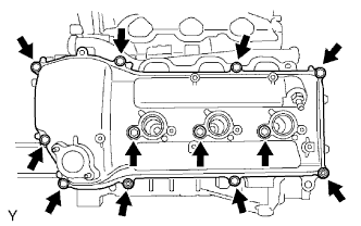 |
Install the cylinder head cover with the 10 bolts and 2 nuts. Uniformly tighten the bolts and nuts in several passes.
| 56. INSTALL OIL CONTROL VALVE FILTER |
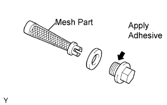 |
Check that no foreign objects on the mesh part of the 2 filters.
Install 2 new gaskets to each new plug.
Insert the filters to the plugs.
Apply adhesive to 2 or 3 threads of the plugs.
Install the plugs to each cylinder head.
| 57. INSTALL CRANKSHAFT POSITION SENSOR |
Install the crankshaft position sensor with the bolt.
| 58. INSTALL VVT SENSOR |
Apply a light coat of engine oil to the O-ring of each VVT sensor.
Install the 2 VVT sensors with the 2 bolts.
| 59. INSTALL CYLINDER BLOCK WATER DRAIN COCK |
 |
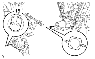
Apply adhesive to 2 or 3 threads of the drain cocks end.
 |
After applying the specified torque, rotate the drain cocks clockwise as shown in the illustration.
| 60. INSTALL OIL DIPSTICK GUIDE |
 |
Install a new O-ring to the oil level gauge guide.
Apply a light coat of engine oil to the O-ring.
Push in the oil level gauge guide end into the guide hole of the oil pan.
Install the oil dipstick gauge guide with the bolt.
| 61. INSTALL NO. 2 ENGINE HANGER |
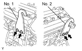 |
Install the engine hanger with the 2 bolts.
| 62. INSTALL NO.1 ENGINE HANGER |
Install the engine hanger with the 2 bolts.
