ENGINE UNIT > INSPECTION |
| 1. INSPECT CAMSHAFT (for Bank 1) |
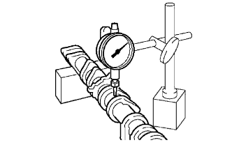 |
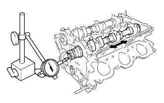
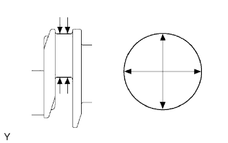
Inspect the camshaft for runout.
Place the camshaft on V-blocks.
Using a dial indicator, measure the circle runout at the center journal.
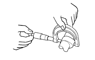 |
Inspect the cam lobes.
Using a micrometer, measure the cam lobe height.
| Camshaft | Cam lobe height |
| Intake | 44.168 to 44.268 mm (1.7389 to 1.7428 in.) |
| Exhaust | 44.580 to 44.680 mm (1.7551 to 1.7591 in.) |
| Camshaft | Cam lobe height |
| Intake | 44.018 mm (1.7330 in.) |
| Exhaust | 44.430 mm (1.7492 in.) |
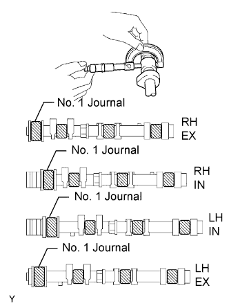 |
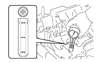
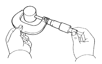
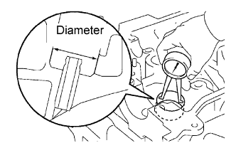
Inspect the camshaft journals.
Using a micrometer, measure the journal diameter.
| Journal | Diameter |
| No. 1 journal | 35.971 to 35.985 mm (1.4162 to 1.4167 in.) |
| Other journal | 22.959 to 22.975 mm (0.9039 to 0.9045 in.) |
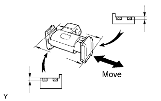
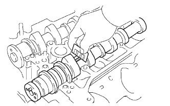
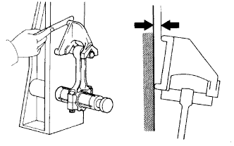
| 2. INSPECT CAMSHAFT TIMING GEAR (for Bank 1) |
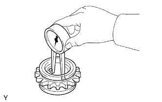
Fix the intake camshaft with a vise.
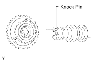 |
Align the knock pin hole in the camshaft timing gear assembly with the knock pin of the camshaft, and install the camshaft timing gear assembly with the bolt.
Confirm the camshaft timing gear assembly is locked.
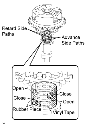 |
Release the lock pin.
Cover 4 oil paths of cam journal with vinyl tape as shown in the illustration.
Break through the tapes of the advance side path and the retard side path on the opposite side of the groove.
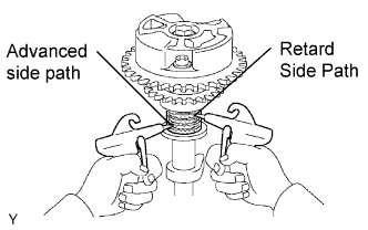 |
Put air pressure into 2 broken paths (the advance side path and the retard side path) with about 200 kPa (2.0 kgf/cm2, 28 psi).
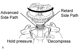 |
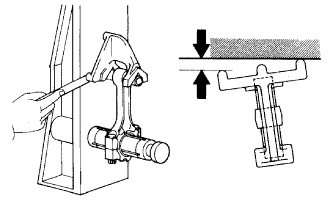
Confirm if the camshaft timing gear assembly rotates in the timing advance direction when weakening the air pressure of the timing retard path.
When the camshaft timing gear comes to the most advanced position, take out the air pressure of the timing retard side path, and then, take out that of timing advance side path.
Check the smooth revolution.
Except the position where the lock pin meets at the most retard angle, let the camshaft timing gear assembly turn back and forth and check the movable range and that there is no disturbance.
Check the lock in the most retarded position.
Confirm that the camshaft timing gear assembly is locked at the most retarded position.
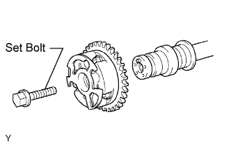 |
Remove the set bolt and camshaft timing gear assembly.
| 3. INSPECT CAMSHAFT (for Bank 2) |
|
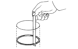
Inspect the camshaft for runout.
Place the camshaft on V-blocks.
Using a dial indicator, measure the circle runout at the center journal.
|
Inspect the cam lobes.
Using a micrometer, measure the cam lobe height.
| Camshaft | Cam lobe height |
| Intake | 44.168 to 44.268 mm (1.7389 to 1.7428 in.) |
| Exhaust | 44.580 to 44.680 mm (1.7551 to 1.7591 in.) |
| Camshaft | Cam lobe height |
| Intake | 44.018 mm (1.7330 in.) |
| Exhaust | 44.430 mm (1.7492 in.) |
|
Inspect the camshaft journals.
Using a micrometer, measure the journal diameter.
| Journal | Diameter |
| No. 1 journal | 35.971 to 35.985 mm (1.4162 to 1.4167 in.) |
| Other journal | 22.959 to 22.975 mm (0.9039 to 0.9045 in.) |
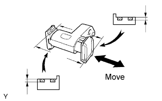
| 4. INSPECT CAMSHAFT TIMING GEAR (for Bank 2) |
Fix the intake camshaft with a vise.
|
Align the knock pin hole in the camshaft timing gear assembly with the knock pin of the camshaft, and install the camshaft timing gear assembly with the bolt.
Confirm the camshaft timing gear assembly is locked.
|
Release the lock pin.
Cover 4 oil paths of cam journal with vinyl tape as shown in the illustration.
Break through the tapes of the advance side path and the retard side path on the opposite side of the groove.
|
Put air pressure into 2 broken paths (the advance side path and the retard side path) with about 200 kPa (2.0 kgf/cm2, 28 psi).
|
Confirm if the camshaft timing gear assembly rotates in the timing advance direction when weakening the air pressure of the timing retard path.
When the camshaft timing gear comes to the most advanced position, take out the air pressure of the timing retard side path, and then take out that of timing advance side path.
Check the smooth revolution.
Except the position where the lock pin meets at the most retard angle, let the camshaft timing gear assembly turn back and forth and check the movable range and that there is no disturbance.
Check the lock in the most retarded position.
Confirm that the camshaft timing gear assembly is locked at the most retarded position.
|
Remove the set bolt and camshaft timing gear assembly.
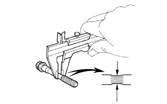
| 5. INSPECT CYLINDER HEAD SET BOLT |
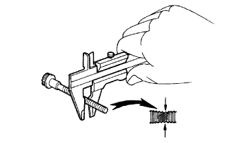 |
Using a vernier caliper, measure the thread outside diameter of the bolt.
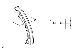
| 6. INSPECT CHAIN |
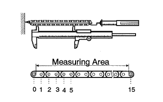 |
Using a spring scale, pull the chain with 147 N (15.0 kgf, 33.1 lbf). Using a vernier caliper, measure the length of 15 links of the chain.
| 7. INSPECT NO. 2 CHAIN |
|
Using a spring scale, pull the chain with 147 N (15.0 kgf, 33.1 lbf). Using a vernier caliper, measure the length of 15 links of the chain.
| 8. INSPECT CAMSHAFT TIMING GEAR |
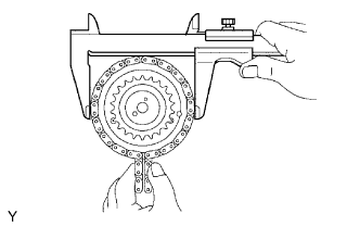 |
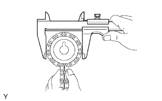
Wrap the No. 1 chain around the larger gear of camshaft timing gear assembly.
Using a vernier caliper, measure the timing gear with the chain.
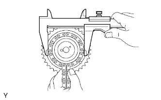 |
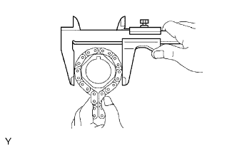
Wrap the No. 2 chain around the smaller gear of camshaft timing gear assembly.
Using a vernier caliper, measure the timing gear with the chain.
| 9. INSPECT CAMSHAFT TIMING SPROCKET |
 |
Wrap the No. 2 chain around the camshaft timing gear.
Using a vernier caliper, measure the camshaft timing gear diameter with the chain .
| 10. INSPECT CRANKSHAFT TIMING SPROCKET |
 |
Wrap the No. 1 chain around the crankshaft timing gear.
Using a vernier caliper, measure the crankshaft timing gear diameter with the chain.
| 11. INSPECT NO. 1 IDLE GEAR |
|
Wrap the No. 1 chain around the idle gear.
Using a vernier caliper, measure the idle gear with the chain.
| 12. INSPECT IDLE GEAR SHAFT OIL CLEARANCE |
 |
Using a micrometer, measure the idle gear shaft diameter.
 |
Using a caliper gauge, measure the inside diameter of the idle gear.
Subtract the idle gear shaft diameter measurement from the idle gear inside diameter measurement.
| 13. INSPECT NO. 1 CHAIN TENSIONER |
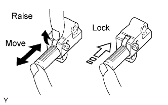 |
Check that the plunger moves smoothly when the ratchet pawl is raised with finger.
Release the ratchet pawl and check that the plunger is locked in place by the ratchet pawl and does not move when pushed with finger.
| 14. INSPECT NO. 2 CHAIN TENSIONER |
 |
Check that the plunger moves smoothly.
Measure the worn depth of the chain tensioner slipper.
| 15. INSPECT NO. 3 CHAIN TENSIONER |
 |
Check that the plunger moves smoothly.
Measure the worn depth of the chain tensioner slipper.
| 16. INSPECT CHAIN TENSIONER SLIPPER |
 |
Measure the worn depth of the chain tensioner slipper.
| 17. INSPECT NO. 1 CHAIN VIBRATION DAMPER |
 |
Measure the worn depth of the No. 1 chain vibration damper.
| 18. INSPECT NO. 2 CHAIN VIBRATION DAMPER |
 |
Measure the worn depth of the No. 2 chain vibration damper.
| 19. INSPECT CYLINDER HEAD |
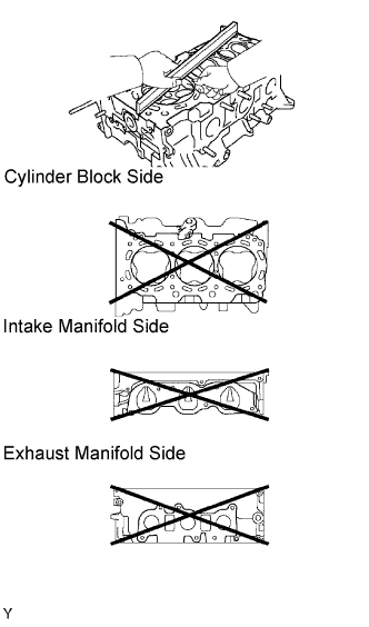 |
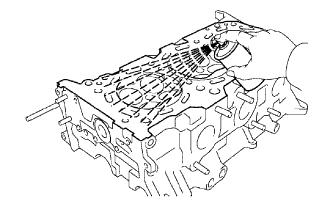
Inspect for flatness.
Using a precision straightedge and feeler gauge, measure the surfaces contacting the cylinder block and manifolds for warpage.
 |
Inspect for cranks.
Using a dye penetrant, check the combustion chamber, intake ports, exhaust ports and cylinder block surface for cracks.
If cracked, replace the cylinder head.
| 20. INSPECT VALVE |
 |
Inspect for valve stem diameter.
Using a micrometer, measure the diameter of the valve stem.
| Item | Specified Condition |
| Intake | 5.470 to 5.485 mm (0.2154 to 0.2159 in.) |
| Exhaust | 5.465 to 5.480 mm (0.2152 to 0.2158 in.) |
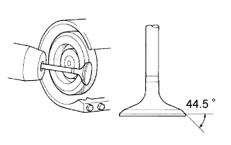 |
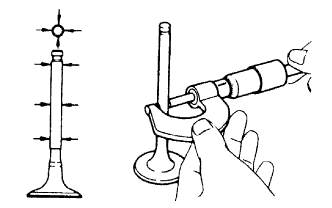
Inspect for valve face angle.
Grind the valve enough to remove pits and carbon.
Check that the valve is ground to the correct valve face angle.
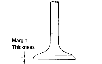 |
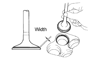
Inspect for valve head margin thickness.
Using a vernier calipers, check the valve head margin thickness.
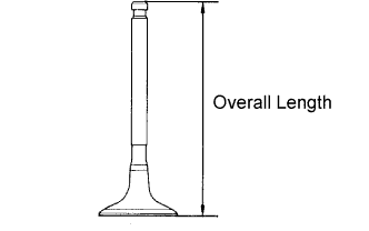 |
Inspect for overall length.
Using a vernier calipers, check the overall length.
| Item | Specified Condition |
| Intake | 106.95 mm (4.2106 in.) |
| Exhaust | 105.80 mm (4.1654 in.) |
| Item | Specified Condition |
| Intake | 106.40 mm (4.1890 in.) |
| Exhaust | 105.30 mm (4.1457 in.) |
 |
Inspect for valve stem tip.
Check the surface of the valve stem tip for wear.
| 21. CLEAN VALVE SEAT |
 |
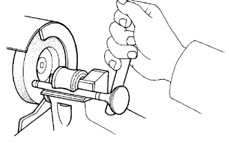
Using a 45° carbide cutter, resurface the valve seats.
Remove only enough metal to clean the valve seats.
| 22. INSPECT VALVE SEAT |
 |
Apply a light coat of Prussian blue (or white lead) to the valve face.
Lightly press the valve against the valve seat.
Check the valve face and seat according to the following procedure.
If blue appears 360° around the face, the valve is concentric.
If not, replace the valve.
If blue appears 360° around the valve seat, the guide and face are concentric.
If not, resurface the valve seat.
Check that the seat contact is in the middle of the valve face with these width.
| 23. INSPECT COMPRESSION SPRING |
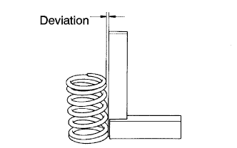 |
Inspect for squareness.
Using a steel square, measure the squareness of the inner compression spring.
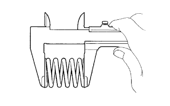 |
Inspect for free length.
Using a vernier calipers, measure the free length of the inner compression spring.
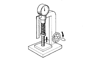 |
Inspect for tension.
Using a spring tester, measure the tension of the inner compression spring at the specified installed length.
| 24. INSPECT VALVE GUIDE BUSH OIL CLEARANCE |
 |
Using a caliper gauge, measure the inside diameter of the valve guide bush.
Subtract the valve stem diameter measurement (see "INSPECT VALVE: Inspect valve stem diameter" procedures above) from the valve guide bush inside diameter measurement.
| Item | Specified Condition |
| Intake | 0.025 to 0.060 mm (0.0010 to 0.0024 in.) |
| Exhaust | 0.030 to 0.065 mm (0.0012 to 0.0026 in.) |
| Item | Specified Condition |
| Intake | 0.08 mm (0.0031 in.) |
| Exhaust | 0.10 mm (0.0039 in.) |
| 25. INSPECT VALVE LIFTER |
 |
Using a micrometer measure the valve lifter diameter.
| 26. INSPECT VALVE LIFTER OIL CLEARANCE |
 |
Using a caliper gauge, measure the lifter bore diameter of the cylinder head.
Subtract the valve lifter diameter measurement (see "INSPECT VALVE LIFTER" procedures above) from the lifter bore diameter measurement.
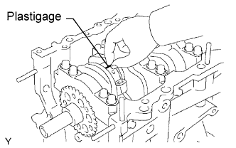
| 27. INSPECT CAMSHAFT OIL CLEARANCE |
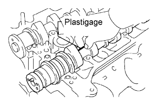 |
Clean the camshaft bearing caps, camshaft bearings and camshaft journals.
Install the camshaft bearing.
Place the camshaft on the cylinder head.
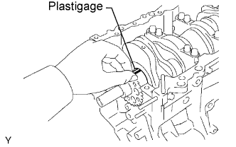
Lay a strip of Plastigage across each of the camshaft journals.
Install the camshaft bearing caps.
Remove the camshaft bearing caps.
 |
Measure the Plastigage at its widest point.
| Item | Specified Condition |
| No. 1 (Intake) | 0.008 to 0.038 mm (0.0003 to 0.0015 in.) |
| No. 1 (Exhaust) | 0.040 to 0.079 mm (0.0016 to 0.0031 in.) |
| Others | 0.025 to 0.062 mm (0.0010 to 0.0024 in.) |
| Item | Specified Condition |
| No. 1 | 0.040 to 0.079 mm (0.0016 to 0.0031 in.) |
| Others | 0.025 to 0.062 mm (0.0010 to 0.0024 in.) |
| Item | Specified Condition |
| No. 1 | 0.07 mm (0.0028 in.) |
| Others | 0.10 mm (0.0039 in.) |
| Item | Specified Condition |
| Cylinder head journal bore diameter | 40.009 to 40.017 mm (1.5752 to 1.5755 in.) |
| Camshaft bearing center wall thickness (Mark "2") | 2.004 to 2.008 mm (0.0789 to 0.0791 in.) |
| Camshaft journal diameter | 35.971 to 35.985 mm (1.4165 to 1.4167 in.) |
Remove the Plastigage completely.
Remove the camshafts.
Remove the camshaft bearing.
| 28. INSPECT CAMSHAFT THRUST CLEARANCE |
 |
Install the camshafts.
Using a dial indicator, measure the thrust clearance while moving the camshaft back and forth.
| 29. INSPECT CONNECTING ROD THRUST CLEARANCE |
 |
Using a dial indicator, measure the thrust clearance while moving the connecting rod back and forth.
| 30. INSPECT CONNECTING ROD OIL CLEARANCE |
Check the matchmarks on the connecting rod and cap are aligned to ensure correct reassemble.
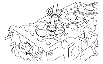
Using SST, remove the 2 connecting rod cap bolts.
Clean the crank pin, bearing and connecting rod.
Check the crank pin and bearing for pitting and scratches.
 |
Lay a strip of Plastigage across the crank pin.
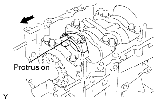 |
Check that the protrusion of the connecting rod cap is facing in the correct direction.
Apply a light coat of engine oil on the threads and under the heads of the connecting rod cap bolts.
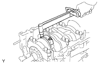 |
Using SST, tighten the bolts in several passes by the specified torque.
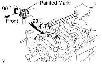 |
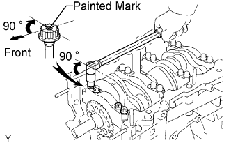
Mark the front side of the each connecting cap bolt with paint.
Retighten the cap bolts by 90°shown in the illustration.
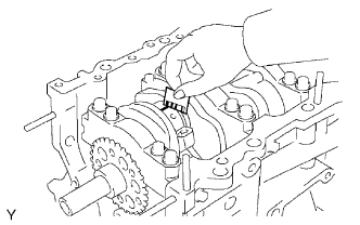
Remove the 2 bolts, connecting rod cap and lower bearing.
 |
Measure the Plastigage at its widest point.
 |
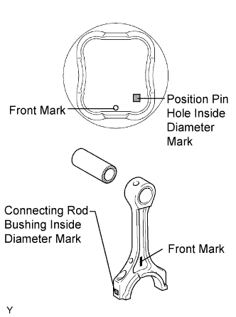
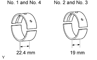
If replace the bearing, replace it with one having the same number as marked on the connecting rod. There are 4 sizes of standard bearings, marked 1, 2, 3 and 4 accordingly.
| Mark | Specified Condition |
| 1 | 1.484 to 1.487 mm (0.0584 to 0.0585 in.) |
| 2 | 1.487 to 1.490 mm (0.0585 to 0.0587 in.) |
| 3 | 1.490 to 1.493 mm (0.0587 to 0.0588 in.) |
| 4 | 1.493 to 1.496 mm (0.0588 to 0.0589 in.) |
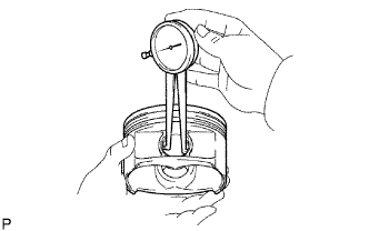
| 31. INSPECT CRANKSHAFT THRUST CLEARANCE |
 |
Using a dial indicator, measure the thrust clearance while prying the crankshaft back and forth with a screwdriver.
| 32. INSPECT CYLINDER BLOCK FOR FLATNESS |
 |
Using a precision straightedge and feeler gauge, measure the surface contacting the cylinder head gasket for warpage.
| 33. INSPECT CYLINDER BORE |
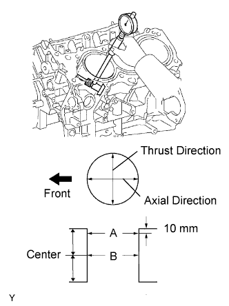 |
Using a cylinder gauge, measure the cylinder bore diameter at positions A and B in the thrust and axial directions.
| 34. INSPECT PISTON |
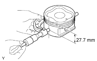 |
Using a micrometer, measure the piston diameter at right angles to the piston pin center line, 27.7 mm (1.091 in.) from the piston head.
| 35. INSPECT PISTON OIL CLEARANCE |
Subtract the piston diameter measurement from the cylinder bore diameter measurement.
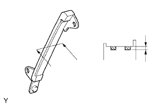
| 36. INSPECT CONNECTING ROD |
 |
Using a rod aligner and feeler gauge, check the connecting rod alignment.
Check for out-of alignment.
 |
Check of twist.
| 37. INSPECT PISTON PIN OIL CLEARANCE |
 |
Using a caliper gauge, measure the inside diameter of the piston pin hole.
| Mark | Specified Condition |
| A | 22.001 to 22.004 mm (0.8662 to 0.8663 in.) |
| B | 22.005 to 22.007 mm (0.8663 to 0.8664 in.) |
| C | 22.008 to 22.010 mm (0.8665 to 0.8665 in.) |
 |
Using a micrometer, measure the piston pin diameter.
| Mark | Specified Condition |
| A | 21.997 to 22.000 mm (0.8660 to 0.8661 in.) |
| B | 22.001 to 22.003 mm (0.8661 to 0.8663 in.) |
| C | 22.004 to 22.006 mm (0.8663 to 0.8664 in.) |
 |
Using a caliper gauge, measure the inside diameter of the connecting rod bushing.
| Mark | Specified Condition |
| A | 22.005 to 22.008 mm (0.8663 to 0.8665 in.) |
| B | 22.009 to 22.011 mm (0.8665 to 0.8666 in.) |
| C | 22.012 to 22.014 mm (0.8666 to 0.8667 in.) |
Subtract the piston pin diameter measurement from the piton pin hole diameter measurement.
 |
Subtract the piston pin diameter measurement from the bushing inside diameter measurement.
| 38. INSPECT RING GROOVE CLEARANCE |
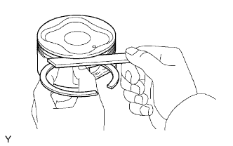 |
Using a feeler gauge, measure the clearance between a new piston ring and the wall of the ring groove.
| Ring | Groove Clearance |
| No.1 | 0.02 to 0.07 mm (0.0008 to 0.0028 in.) |
| No.2 | 0.02 to 0.06 mm (0.0008 to 0.0024 in.) |
| Oil | 0.07 to 0.15 mm (0.0028 to 0.0060 in.) |
| 39. INSPECT PISTON RING END GAP |
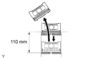 |
Using a piston, push the piston ring a little beyond the bottom of the ring travel, 110 mm (4.33 in.) from the top of the cylinder block.
 |
Using a feeler gauge, measure the end gap.
| Ring | End Gap |
| No.1 | 0.30 to 0.40 mm (0.0118 to 0.0157 in.) |
| No.2 | 0.40 to 0.50 mm (0.0157 to 0.0197 in.) |
| Oil (side rail) | 0.10 to 0.40 mm (0.0039 to 0.0157 in.) |
| Ring | End Gap |
| No.1 | 1.0 mm (0.039 in.) |
| No.2 | 1.1 mm (0.043 in.) |
| Oil (side rail) | 1.0 mm (0.039 in.) |
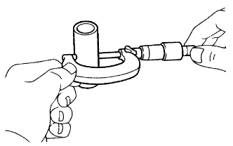
| 40. INSPECT CONNECTING ROD BOLT |
 |
Using a vernier caliper, measure the tension portion diameter of the bolt.
| 41. INSPECT CRANKSHAFT BEARING CAP SET BOLT |
|
Using a vernier caliper, measure the tension portion diameter of the bolt.
| 42. INSPECT CRANKSHAFT |
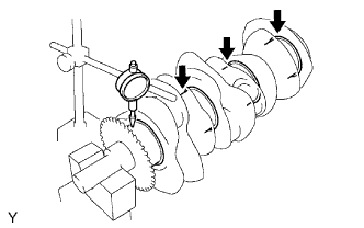 |
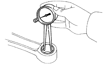
Using a dial indicator and V-blocks, measure the circle runout, as shown in the illustration.
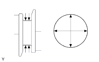 |
Using a micrometer, measure the diameter of each main journal.
Check each main journal for taper and out-of-round as shown.
 |
Using a micrometer, measure the diameter of each crank pin.
Check each crank pin for taper and out-of-round as shown.
| 43. INSPECT CRANKSHAFT OIL CLEARANCE |
 |
Clean each main journal and bearing.
 |
Align the bearing claw with the claw groove of the cylinder block, and push in the 4 upper bearings.
 |
Align the bearing claw with the claw groove of the main bearing cap, and push in the 4 lower bearings.
Place the crankshaft on the cylinder block.
 |
Lay a strip of Plastigage across each journal.
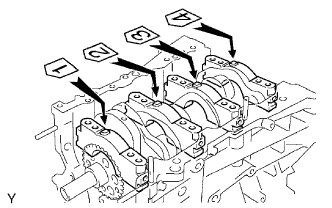 |
Examine the front marks and numbers and install the bearing caps on the cylinder block.
Apply a light coat of engine oil on the threads and under the head of bearing cap bolts.
Temporarily install the 8 main bearing cap bolts to the inside positions.
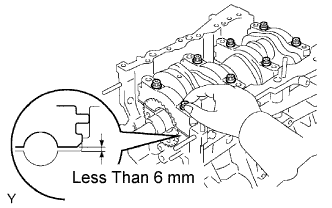 |
Insert the main bearing cap with hand until the clearance between the main bearing cap and the cylinder block will become less than 6 mm (0.23 in.) by making the 2 internal bearing cap bolts as a guide.
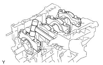 |
Using a plastic-faced hammer, lightly tap the bearing cap to ensure a proper fit.
Apply a light coat of engine oil on the threads and under the head of main bearing cap bolts.
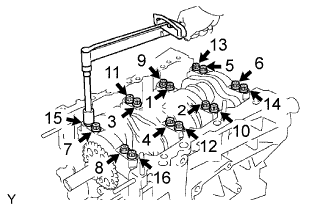 |
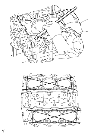
Install and uniformly tighten the 16 main bearing cap bolts in several passes, in the sequence shown.
 |
Mark the front side of the bearing cap bolts with paint.
Retighten the bearing cap bolts by 90° in the sequence shown.
Check that the painted mark is now at a 90° angle to the front.
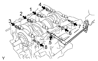 |
Install and uniformly tighten the 8 main bearing cap bolts in several passes, in the sequence shown.
Remove the main bearing caps.
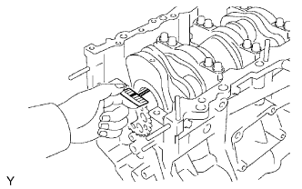 |
Measure the Plastigage at its widest point.
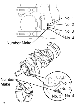 |
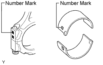
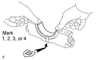
Using a bearing, replace it with one having the same number. If the number of the bearing cannot be determined, select the correct bearing by adding together the numbers imprinted on the cylinder block and crankshaft, then refer to the table below for the appropriate bearing number. There are 5 size of standard bearings, marked 1, 2, 3, 4 and 5 accordingly.
| Cylinder block (A) + Crankshaft | 0 to 5 | 6 to 11 | 12 to 17 | 18 to 23 | 24 to 28 |
| Use Bearing | 1 | 2 | 3 | 4 | 5 |
| Mark | Specified Condition |
| 00 | 77.000 mm (3.0315 in.) |
| 01 | 77.001 mm (3.0315 in.) |
| 02 | 77.002 mm (3.0316 in.) |
| 03 | 77.003 mm (3.0316 in.) |
| 04 | 77.004 mm (3.0317 in.) |
| 05 | 77.005 mm (3.0317 in.) |
| 06 | 77.006 mm (3.0317 in.) |
| 07 | 77.007 mm (3.0318 in.) |
| 08 | 77.008 mm (3.0318 in.) |
| 09 | 77.009 mm (3.0319 in.) |
| 10 | 77.010 mm (3.0319 in.) |
| 11 | 77.011 mm (3.0319 in.) |
| 12 | 77.012 mm (3.0320 in.) |
| 13 | 77.013 mm (3.0320 in.) |
| 14 | 77.014 mm (3.0320 in.) |
| 15 | 77.015 mm (3.0321 in.) |
| 16 | 77.016 mm (3.0321 in.) |
| Mark | Specified Condition |
| 00 | 71.999 to 72.000 mm (2.8346 to 2.8346 in.) |
| 01 | 71.998 to 71.999 mm (2.8346 to 2.8346 in.) |
| 02 | 71.997 to 71.998 mm (2.8345 to 2.8346 in.) |
| 03 | 71.996 to 71.997 mm (2.8345 to 2.8346 in.) |
| 04 | 71.995 to 71.996 mm (2.8344 to 2.8345 in.) |
| 05 | 71.994 to 71.995 mm (2.8344 to 2.8344 in.) |
| 06 | 71.993 to 71.994 mm (2.8343 to 2.8344 in.) |
| 07 | 71.992 to 71.993 mm (2.8343 to 2.8343 in.) |
| 08 | 71.991 to 71.992 mm (2.8343 to 2.8343 in.) |
| 09 | 71.990 to 71.991 mm (2.8343 to 2.8343 in.) |
| 10 | 71.989 to 71.990 mm (2.8342 to 2.8343 in.) |
| 11 | 71.988 to 71.989 mm (2.8342 to 2.8342 in.) |
| Mark | Specified Condition |
| 01 | 2.488 to 2.491 mm (0.0980 to 0.0981 in.) |
| 02 | 2.491 to 2.494 mm (0.0981 to 0.0982 in.) |
| 03 | 2.494 to 2.497 mm (0.0982 to 0.0983 in.) |
| 04 | 2.497 to 2.500 mm (0.0982 to 0.0984 in.) |
| 05 | 2.500 to 2.503 mm (0.0984 to 0.0985 in.) |
