ENGINE UNIT > REPLACEMENT |
| 1. REMOVE TIMING CHAIN COVER OIL SEAL |
Using a screwdriver, pry out the oil seal.
| 2. INSTALL TIMING CHAIN COVER OIL SEAL |
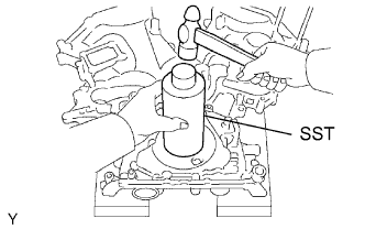 |
Using SST and a hammer, tap in a new oil seal until its surface is flush with the timing chain cover edge.
Apply MP grease to the oil seal lip.
| 3. REMOVE REAR ENGINE OIL SEAL |
 |
Using a screwdriver and hammer, tap out the oil seal.
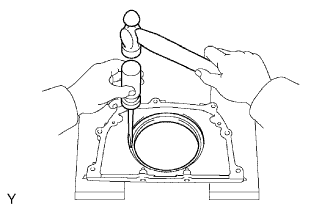
| 4. INSTALL REAR ENGINE OIL SEAL |
 |
Using SST and a hammer, tap in a new oil seal until its surface is flush with the rear oil seal retainer edge.
Apply MP grease to the oil seal lip.
| 5. REMOVE VALVE GUIDE BUSH |
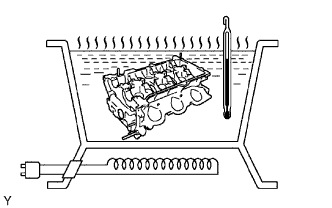 |
Gradually heat the cylinder head to 80 to 100°C (176 to 212°F).
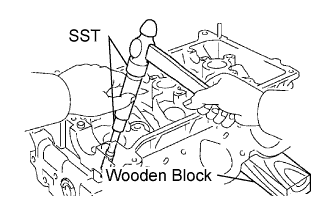 |
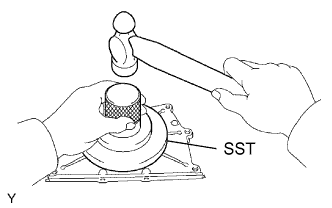
Place the cylinder head on the wooden block.
Using SST, tap out the valve guide bush.
| 6. INSTALL VALVE GUIDE BUSH |
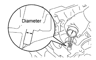 |
Using a caliper gauge, measure the bush bore diameter of the cylinder head.
| Valve | Specified Condition |
| STD | 10.333 to 10.344 mm (0.4068 to 0.4072 in.) |
| O/S 0.05 | 10.383 to 10.394 mm (0.4088 to 0.4092 in.) |
|
Gradually heat the cylinder head to 80 to 100°C (176 to 212°F).
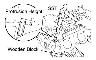 |
Place the cylinder head on the wooden block.
Using SST, tap in a new valve guide bush to the specified protrusion height.
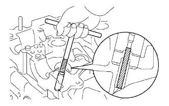 |
Using a sharp 5.5 mm reamer, ream the valve guide bush to obtain the standard specified clearance between the valve guide bush and valve stem.
| Valve | Specified Condition |
| Intake | 0.025 to 0.060 mm (0.0010 to 0.0024 in.) |
| Exhaust | 0.030 to 0.065 mm (0.0012 to 0.0026 in.) |
| 7. REMOVE CONNECTING ROD SMALL END BUSH |
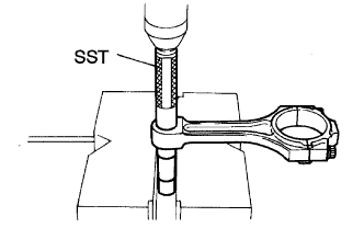 |
Using SST and a press, press out the bush.
| 8. INSTALL CONNECTING ROD SMALL END BUSH |
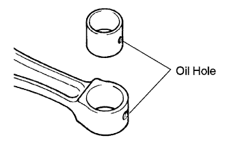 |
Align the oil holes of a new bush and the connecting rod.
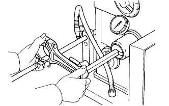
|
Using SST and a press, press in the bush.
 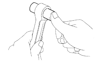 |
Using a pin hole grinder, hone the bush to obtain the standard specified clearance between the bush and piston pin.
