ENGINE ASSEMBLY > REMOVAL |
| 1. DISCHARGE FUEL SYSTEM PRESSURE |
Disconnect the cable from the negative (-) battery terminal.
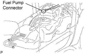 |
Disconnect the fuel pump connector.
Connect the cable to the negative (-) battery terminal.
Start the engine. After the engine has stopped on its own, turn the ignition switch OFF.
Crank the engine again, then check that the engine does not start.
Loosen the fuel tank cap, then discharge the pressure in the fuel tank completely.
Connect the fuel pump connector.
| 2. DISCONNECT CABLE FROM NEGATIVE BATTERY TERMINAL |
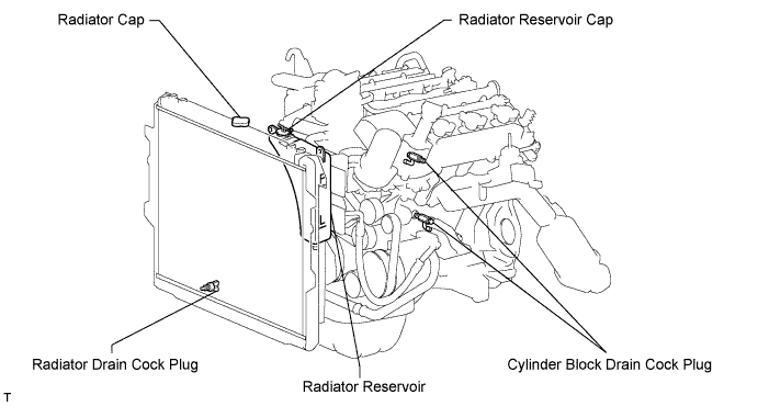
| 3. DRAIN ENGINE COOLANT |
Remove the radiator cap.
Loosen the 2 cylinder block drain cock plugs and radiator drain plug, and then the coolant.
| 4. DRAIN ENGINE OIL |
Remove the engine under cover.
Remove the oil pan drain plug and drain the engine oil into a container.
| 5. REMOVE BATTERY |
| 6. REMOVE HOOD |
Disconnect the windshield washer hose.
Remove the 4 bolts and hood.
| 7. REMOVE V-BANK COVER |
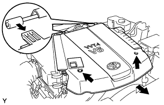 |
Remove the 2 nuts and the V-bank cover.
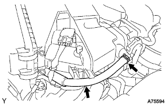
| 8. DISCONNECT NO. 2 VENTILATION HOSE |
 |
| 9. REMOVE AIR CLEANER |
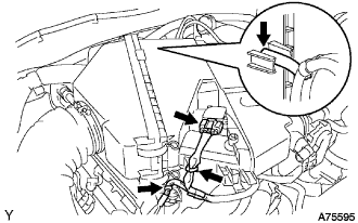 |
Disconnect the vacuum hose.
Disconnect the MAF meter connector.
Remove the 2 wire harness clamps.
 |
Loosen the 2 hose clamps.
Remove the 2 bolts and air cleaner.
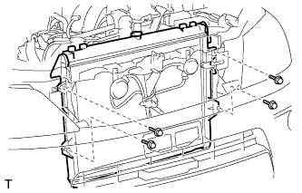
| 10. REMOVE RADIATOR GRILLE |
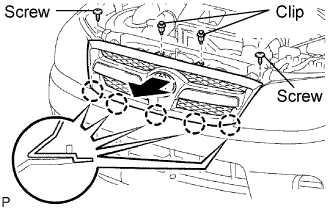 |
Using a clip remover, remove the 2 clips.
Remove the 2 screws.
Pull the radiator grille in the direction indicated by the arrow in the illustration to detach the 5 claws and remove the radiator grille.
| 11. REMOVE RADIATOR SIDE DEFLECTOR RH |
Using a clip remover, remove the 2 clips.
Detach the claw and remove the deflector.
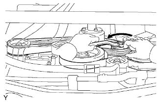
| 12. REMOVE FAN SHROUD |
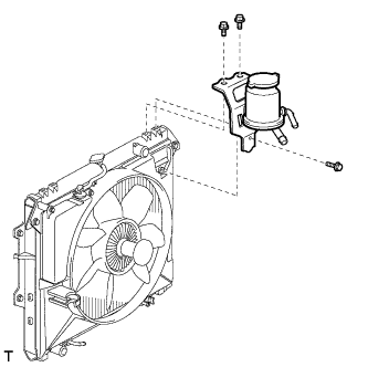 |
Remove the 3 bolts and oil reservoir.
Disconnect the reservoir hose from the radiator tank upper.
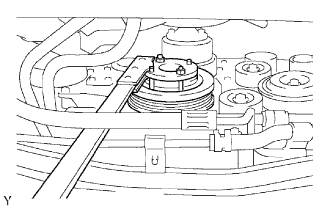
Loosen the 4 nuts holding the fluid coupling fan.
Remove the drive belt (Click here).
Remove the 2 bolts holding the fan shroud.
Remove the 4 nuts of the fluid coupling fan, and then remove the shroud together with the fluid coupling fan.
Remove the fan pulley from the water pump.
| 13. LOOSEN FAN WITH FLUID COUPLING |
| 14. REMOVE DRIVE BELT |
 |
While releasing the belt tension by turning the belt tensioner counterclockwise, remove the V-ribbed belt from the belt tensioner.
| 15. REMOVE FAN WITH FLUID COUPLING |
Remove the 4 bolts and fan with fluid coupling.
| 16. REMOVE FAN PULLEY |
| 17. REMOVE RADIATOR |
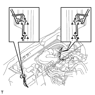 |
Disconnect the 2 front airbag sensor connectors.
Using a clip remover, detach the 4 clamps from the radiator side as shown in the illustration.
 |
Remove the 4 bolts and radiator.
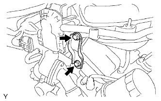
| 18. DISCONNECT VANE PUMP |
 |
Disconnect the oil pressure switch connector.
Remove the 2 bolts, and disconnect the vane pump.
| 19. REMOVE GENERATOR |
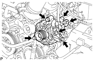 |
Remove the nut and generator wire.
Disconnect the generator connector.
Remove the 2 bolts, adjusting bar and generator.
| 20. DISCONNECT COOLER COMPRESSOR |
| 21. DISCONNECT NO. 1 FUEL PIPE |
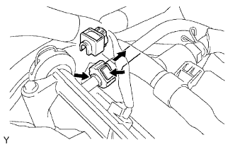 |
Remove the fuel pipe clamp.
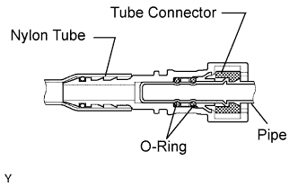
Pinch the tube connector and then pull out the fuel pipe.
| 22. DISCONNECT NO. 2 FUEL PIPE |
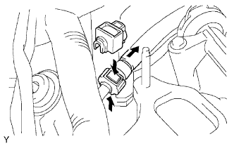 |
Remove the fuel pipe clamp.
Pinch the tube connector and then pull out the fuel pipe.
| 23. DISCONNECT HEATER HOSE |
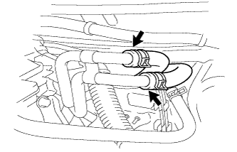 |
Disconnect the hater water inlet hoses.
Disconnect the heater water outlet hose.
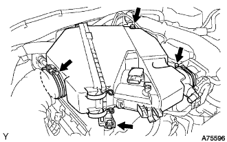
| 24. REMOVE INTAKE AIR SURGE TANK |
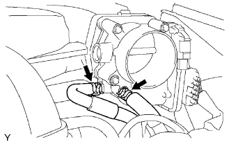 |
Disconnect the 2 water by-pass hose.
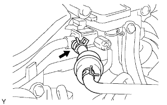 |
Disconnect the fuel vapor feed hose.
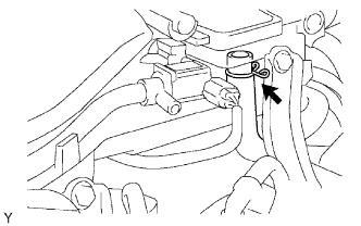 |
Disconnect the ventilation hose.
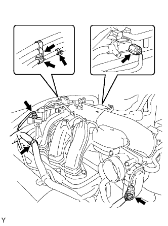 |
Disconnect the 2 VSV connectors.
Disconnect the throttle body with motor connector.
Separate the 3 wire harness clamps and hose clamp.
 |
Remove the 2 bolts and throttle body bracket.
 |
Remove the bolt and oil baffle plate.
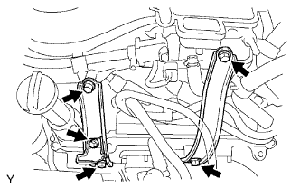
Remove the 4 bolts and 2 surge tank stays.
 |
Remove the 2 nuts.
Using an 8 mm socket hexagon wrench, remove the 4 bolts, intake air surge tank and gasket.
| 25. DISCONNECT ENGINE WIRE |
 |
Disconnect the ECM connectors from the cabin:
Remove the glove compartment door.
Disconnect the 4 ECM connectors.
Disconnect the 4WD control ECU connector.
Remove the bolt and clamp, and disconnect the ground wire.
Remove the bolt and disconnect the ground wire from the frame.
Pull out the engine wire from the cabin.
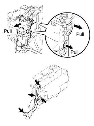 |
Remove the engine room relay block cover (upper).
Remove the engine room relay block cover (side).
Using a screwdriver, detach the 4 claws and remove the relay block cover.
Remove the nut and disconnect the cable from the engine room junction block.
Disconnect the 2 engine room junction block connectors and disconnect the wire clamp.
Remove the bolt and disconnect the wire clamp from the engine mounting bracket front LH
Disconnect the 2 A/F sensor connectors.
Disconnect the A.D.D. connector.
| 26. DISCONNECT NO. 2 ENGINE WIRE |
Disconnect the ground cable from the cylinder block.
| 27. REMOVE FRONT EXHAUST PIPE |
Remove the 2 nuts, pipe support and exhaust pipe.
| 28. REMOVE FRONT FENDER SEAL |
Remove the front tires.
Remove the 10 clips and RH and LH fender seals.
| 29. REMOVE FRONT FENDER APRON SEAL UPPER |
Remove the 10 clips and RH and LH fender seals.
| 30. REMOVE EXHAUST MANIFOLD RH |
Remove the 6 nuts, exhaust manifold and gasket.
| 31. REMOVE EXHAUST MANIFOLD LH |
Remove the 6 nuts, exhaust manifold and gasket.
| 32. REMOVE STARTER |
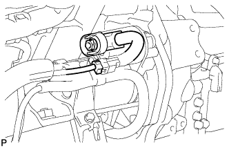 |
Disconnect the starter connector.
Remove the nut and disconnect the starter wire.
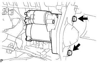 |
Remove the 2 bolts and starter.
| 33. REMOVE AUTOMATIC TRANSMISSION |
4WD:
Remove the automatic transmission from the vehicle (Click here).
2WD:
Remove the automatic transmission from the vehicle (Click here ).
| 34. REMOVE MANUAL TRANSMISSION |
4WD:
Remove the manual transmission from the vehicle (Click here).
2WD:
Remove the manual transmission from the vehicle (Click here).
| 35. REMOVE CLUTCH COVER (for Manual Transmission) |
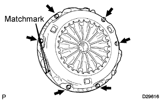 |
Place matchmarks on the clutch cover and flywheel.
Loosen each set bolt one turn at a time until spring tension is released.
Remove the 6 set bolts and pull off the clutch cover.
| 36. REMOVE CLUTCH DISC (for Manual Transmission) |
| 37. REMOVE DRIVE PLATE AND RING GEAR (for Automatic Transmission) |
 |
Using SST, hold the crankshaft.
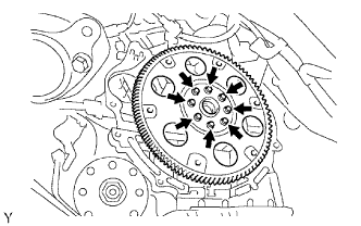 |
Remove the 8 bolts, front spacer, drive plate and rear spacer.
| 38. REMOVE FLYWHEEL (for Manual Transmission) |
|
Using SST, hold the crankshaft.
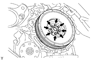 |
Remove the 8 bolts and flywheel.
| 39. REMOVE ENGINE ASSEMBLY |
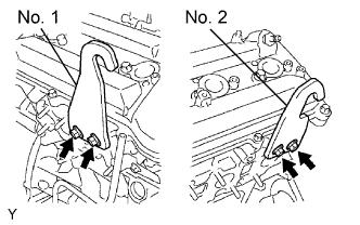 |
Install the 2 engine hangers with the 4 bolts as shown in the illustration.
| Item | Part No |
| No. 1 Engine hanger | 12281-31070 |
| No. 2 Engine hanger | 12282-31050 |
| Bolt | 91671-10825 |
Attach the engine sling device and chain block to the engine hangers.
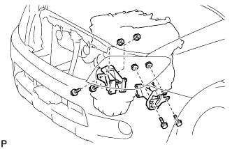 |
Remove the 4 bolts and 4 nuts, holding the engine mounting bracket and frame.
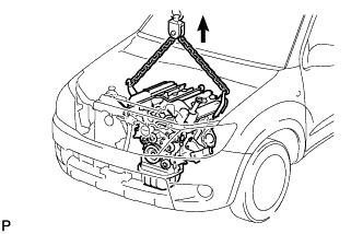 |
Lift the engine out of the vehicle carefully.
| 40. INSTALL ENGINE TO ENGINE STAND |
Place the engine assembly onto the stand.
| 41. REMOVE ENGINE WIRE FROM ENGINE ASSEMBLY |
| 42. REMOVE NO. 1 RADIATOR HOSE |
| 43. REMOVE NO. 2 RADIATOR HOSE |
| 44. REMOVE HEATER WATER HOSE FROM ENGINE ASSEMBLY |
| 45. REMOVE VENTILATION HOSE |
| 46. REMOVE NO. 2 VENTILATION HOSE |
| 47. REMOVE NO. 1 ENGINE MOUNTING BRACKET FRONT RH |
Remove the 4 bolts and engine mounting bracket with engine mounting insulator.
| 48. REMOVE NO. 1 ENGINE MOUNTING BRACKET FRONT LH |
Remove the 3 bolts and engine mounting bracket with engine mounting insulator.
| 49. REMOVE NO. 2 IDLER PULLEY |
Remove the 2 bolts and 2 idler pulleys.
| 50. REMOVE NO. 1 IDLER PULLEY |
Remove the bolt and idler pulley.
| 51. REMOVE IDLER PULLEY |
Remove the 3 bolts and idler pulley.
| 52. REMOVE V-RIBBED BELT TENSIONER |
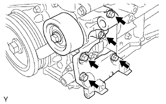 |
Remove the 5 bolts and V-ribbed belt tensioner.
| 53. REMOVE WATER INLET |
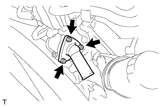 |
Remove the 3 nuts, water inlet with thermostat and gasket.
| 54. REMOVE OIL FILTER BRACKET |
Remove the 3 bolts, 2 oil filter bracket and gasket.
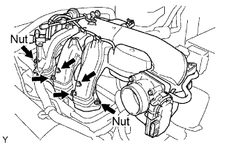
| 55. REMOVE INTAKE MANIFOLD |
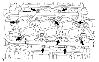 |
Disconnect the 6 fuel injector connectors.
Remove the 10 bolts, intake manifold and 2 gaskets.
| 56. REMOVE CAMSHAFT TIMING OIL CONTROL VALVE |
Remove the 2 bolts and 2 camshaft timing oil control valves.
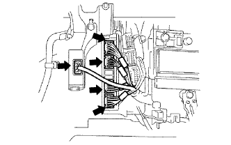
| 57. REMOVE WATER BY-PASS JOINT REAR |
Disconnect the engine coolant temperature sensor connector.
Disconnect the heater hose.
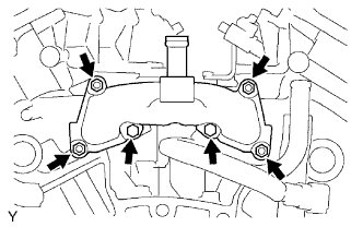 |
Remove the 2 bolts, 4 nuts, water by-pass joint and 2 gaskets.
Remove the O-ring from the water outlet pipe.
| 58. REMOVE OIL FILLER CAP |
| 59. REMOVE OIL FILLER CAP HOUSING |
Remove the 2 nuts, oil filler cap housing and gasket.
| 60. REMOVE IGNITION COIL |
Remove the bolt and ignition coil.
| 61. REMOVE SPARK PLUG |
| 62. REMOVE OIL DIPSTICK GUIDE |
Remove the oil dipstick gauge.
Remove the bolt and pull out the oil dipstick gauge guide.
Remove the O-ring from the oil dipstick gauge guide.
