CAMSHAFT (for Bank 2) > INSTALLATION |
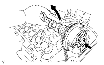
| 1. INSTALL NO. 3 CAMSHAFT |
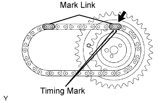 |
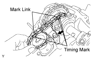
Align the mark link (yellow) with the timing mark (2 dot marks) of the camshaft timing gear as shown in the illustration.
Apply new engine oil to the thrust portion and journal of the camshafts.
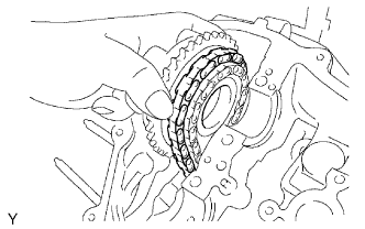 |
Temporarily put the No. 1 chain on the No. 2 chain of the camshaft timing gear.
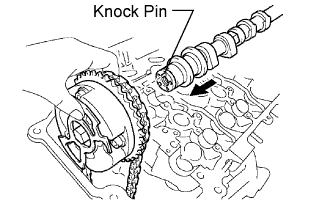 |
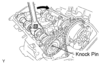
Align the knock pin hole in the camshaft timing gear with the knock pin of the No. 3 camshaft, and insert the No. 3 camshaft into the camshaft timing gear.
Temporarily install the camshaft timing gear set bolt.
 |
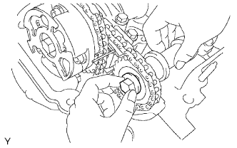
Set the No. 3 camshaft onto the LH cylinder head with the cam lobes of the No. 2 cylinder faced downward as shown in the illustration.
 |
Install the 4 bearing caps in their proper locations.
Apply a light coat of engine oil on the threads and under the heads of the bearing cap bolts.
 |
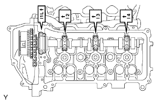
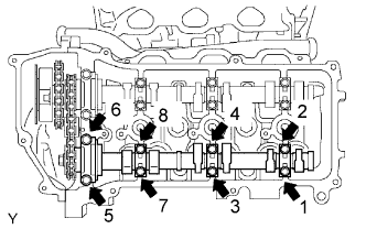
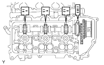
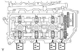
Install and uniformly tighten the 8 bearing cap bolts in several passes in the sequence shown in the illustration.
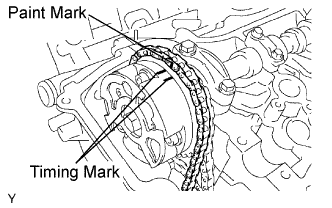 |
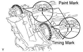
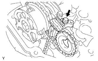
Set the paint mark of the No. 1 chain between the timing marks of the camshaft timing gear.
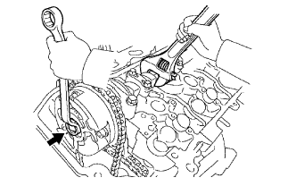 |
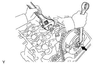
Hold the hexagonal portion of the No. 3 camshaft with a wrench, and tighten the camshaft timing gear set bolt.
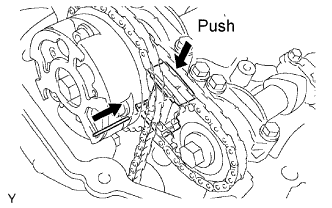
| 2. INSTALL NO. 3 CHAIN TENSIONER |
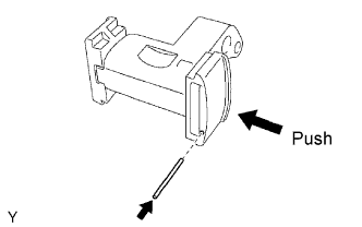 |
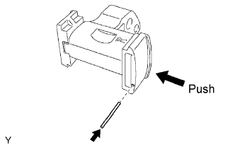
While pushing in the tensioner, insert a diameter of 1.0 mm (0.039 in.) pin into the hole to fix it in place.
 |
Temporarily install the camshaft timing gear and No. 3 chain tensioner and align the mark links (yellow) with the timing marks (1 dot mark and 2 dot mark) of the camshaft timing gears.
Tighten the No. 3 chain tensioner bolt.
| 3. INSTALL NO. 4 CAMSHAFT |
 |
Align the knock pin hole in the camshaft timing gear with the knock pin of the No. 4 camshaft, and insert the No. 4 camshaft into the camshaft timing gear.
Temporarily install the camshaft timing gear set bolt.
 |
Install the 4 bearing caps in their proper locations.
Apply a light coat of engine oil on the threads of the bearing cap bolts.
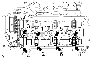 |
Using several steps, install and tighten the 8 bearing cap bolts uniformly in the sequence as shown in the illustration.
 |
Hold the hexagonal portion of the No. 4 camshaft with a wrench, and tighten the camshaft timing gear set bolt.
Remove the pin from the No. 3 chain tensioner.
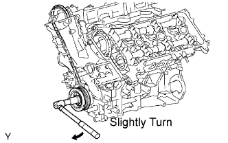 |
Release the chain tension between the camshaft timing gear (RH bank) and crankshaft timing gear by turning the crankshaft pulley clockwise slightly.
| 4. INSTALL NO. 1 CHAIN TENSIONER |
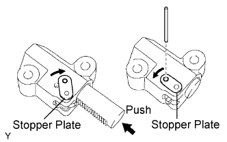 |
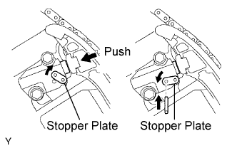
While rotating the stopper plate of the tensioner clockwise, push in the plunger of the tensioner as shown in the illustration.
While rotating the stopper plate of the tensioner counterclockwise, insert a bar of diameter of 3.5 mm (0.138 in.) into the holes in the stopper plate and tensioner to fix the stopper plate.
Install the chain tensioner with the 2 bolts.
| 5. SET NO. 1 CYLINDER TO TDC/COMPRESSION |
 |
Turn the crankshaft pulley, and align its groove with the timing mark 0 of the timing chain cover.
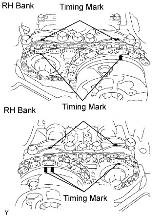 |
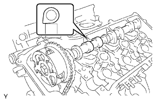
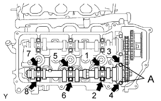
Check that the timing marks of the camshaft timing gears are aligned with the timing marks of the bearing cap as shown in the illustration.
If not, turn the crankshaft 1 complete revolution (360°) and align the timing marks as above.
| 6. INSPECT VALVE CLEARANCE |
 |
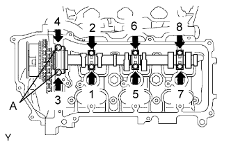
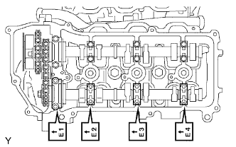
Check the valves indicated in the illustration.
Using a feeler gauge, measure the clearance between the valve lifter and camshaft.
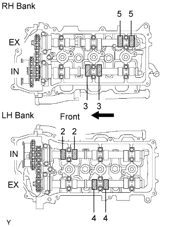 |
Turn the crankshaft 2/3 of a revolution (240°), and check the valves indicated in the illustration.
Using a feeler gauge, measure the clearance between the valve lifter and camshaft.
Record the out-of-specification valve clearance measurements. They will be used later to determine the required replacement valve lifter.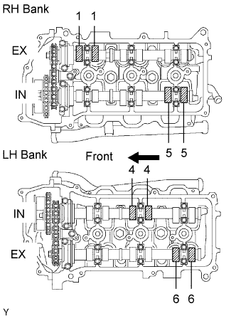
| 7. ADJUST VALVE CLEARANCE |
|
Set No. 1 cylinder to TDC/compression.
Turn the crankshaft pulley, and align the notch with the timing mark 0 of the timing chain cover.
|
Check that the timing marks of the camshaft timing gears are aligned with the timing marks of the bearing cap as shown in the illustration.
If not, turn the crankshaft 1 complete revolution (360°) and align the timing marks as above.
 |
Place paint marks on the No. 1 chain links that correspond with the timing marks of the camshaft timing gears.
Remove the No. 1 chain tensioner.
 |
Remove the 4 bolts, timing chain cover plate and gasket.
 |
While rotating the stopper plate of the tensioner upward, push in the plunger of the chain tensioner as shown in the illustration.
While rotating the stopper plate of the tensioner downward, insert a bar of 3.5 mm (0.138 in.) into the holes in the stopper plate and tensioner to fix the stopper plate.
Remove the 2 bolts and chain tensioner.
Remove the No. 2 camshaft.
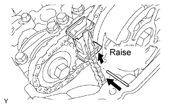 |
While raising up the No. 2 chain tensioner, insert a diameter of 1.0 mm (0.039 in.) into the hole to fix it.
 |
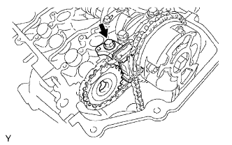
Hold the hexagonal portion of the No. 2 camshaft with a wrench, and remove the camshaft timing gear set bolt.
Separate the camshaft timing gear from the No. 2 camshaft.
 |
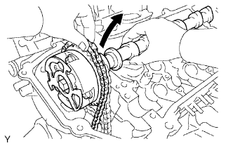
Rotate the camshaft counterclockwise using the wrench so that the cam lobes of the No. 1 cylinder faces upward as shown in the illustration.
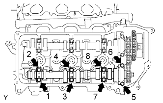 |
Uniformly loosen and remove the 8 bearing cap bolts in several passes in the sequence shown in the illustration.
Remove the 4 bearing caps and No. 2 camshaft.
 |
Remove the No. 2 chain tensioner.
Remove the No. 2 chain tensioner bolt, and then remove the No. 2 chain tensioner and camshaft timing gear.
Remove the No. 1 camshaft.
 |
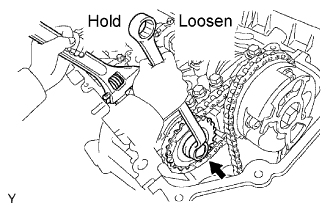
Hold the hexagonal portion of the No. 1 camshaft with a wrench, and loosen the camshaft timing gear set bolt.
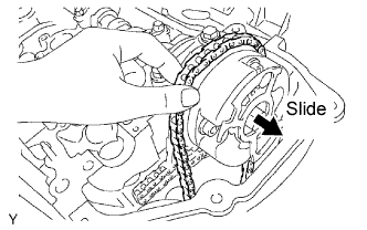 |
Slide the camshaft timing gear and separate the No. 1 chain from the camshaft timing gear.
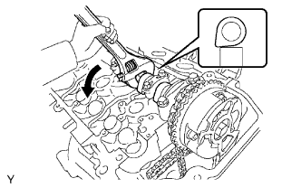 |
Rotate the No. 1 camshaft counterclockwise using the wrench so that the cam lobes of No. 1 cylinder faces upward as shown in the illustration.
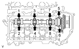 |
Uniformly loosen and remove the 8 bearing cap bolts in several passes in the sequence shown in the illustration.
Remove the 4 bearing caps.
 |
Remove the camshaft timing gear set bolt with the No. 1 camshaft lifted up, and then remove the No. 1 camshaft and camshaft timing gear w/ No. 2 chain.
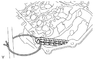 |
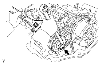
Tie the No. 1 chain with a string as shown in the illustration.
Remove the No. 4 camshaft.
 |
While pushing down the No. 3 chain tensioner, insert a pin of diameter of 1.0 mm (0.039 in.) into the hole to fix it.
|
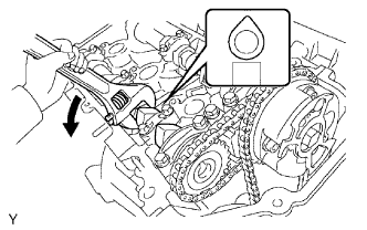
Hold the hexagonal portion of the No. 4 camshaft with a wrench, and remove the camshaft timing gear set bolt.
Separate the camshaft timing gear from the No. 4 camshaft.
 |
Uniformly loosen and remove the 8 bearing cap bolts in several passes in the sequence shown in the illustration.
Remove the 4 bearing caps and No. 4 camshaft.
 |
Remove the No. 3 chain tensioner assembly.
Remove the No. 3 chain tensioner bolt, and then remove the No. 3 chain tensioner and camshaft timing gear.
Remove the No. 3 camshaft sub-assembly
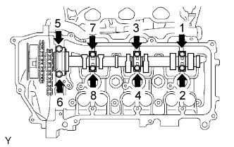 |
Using several steps, loosen and remove the 8 bearing cap bolts uniformly in the sequence as shown in the illustration.
Remove the 4 bearing caps.
 |
Hold the No. 1 chain, and remove the No. 3 camshaft, camshaft timing gear and No. 2 chain.
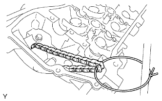 |
Tie the No. 1 chain with a string as shown in the illustration.
Remove the valve lifters.
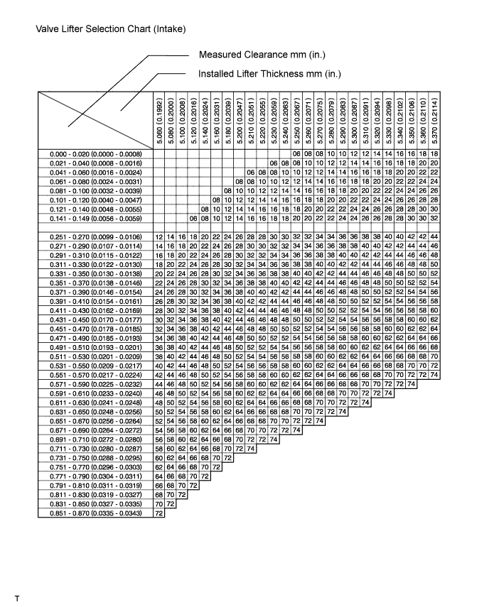
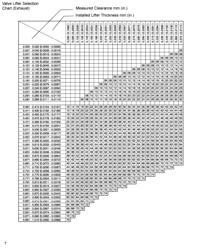
Determine the replacement valve lifter size according to these Formula or Charts:
Using a micrometer, measure the thickness of the removed lifter.
Calculate the thickness of a new lifter so that the valve clearance comes within the specified value.
Select a new intake side lifter with a thickness as close as possible to the calculated value.
Valve lifter selection chart (intake).
Valve lifter selection chart (intake) (continued).
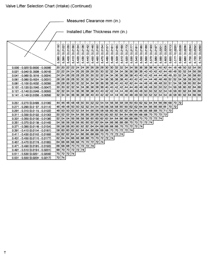
| No. | Thickness | No. | Thickness | No. | Thickness |
| 06 | 5.060 (0.1992) | 30 | 5.300 (0.2087) | 54 | 5.540 (0.2181) |
| 08 | 5.080 (0.2000) | 32 | 5.320 (0.2094) | 56 | 5.560 (0.2189) |
| 10 | 5.100 (0.2008) | 34 | 5.340 (0.2102) | 58 | 5.580 (0.2197) |
| 12 | 5.120 (0.2016) | 36 | 5.360 (0.2110) | 60 | 5.600 (0.2205) |
| 14 | 5.140 (0.2024) | 38 | 5.380 (0.2118) | 62 | 5.620 (0.2213) |
| 16 | 5.160 (0.2031) | 40 | 5.400 (0.2126) | 64 | 5.640 (0.2220) |
| 18 | 5.180 (0.2039) | 42 | 5.420 (0.2134) | 66 | 5.660 (0.2189) |
| 20 | 5.200 (0.2047) | 44 | 5.440 (0.2142) | 68 | 5.680 (0.2236) |
| 22 | 5.220 (0.2055) | 46 | 5.460 (0.2150) | 70 | 5.700 (0.2244) |
| 24 | 5.240 (0.2063) | 48 | 5.480 (0.2157) | 72 | 5.720 (0.2252) |
| 26 | 5.260 (0.2071) | 50 | 5.500 (0.2165) | 74 | 5.740 (0.2260) |
| 28 | 5.280 (0.2079) | 52 | 5.520 (0.2173) |
Valve lifter selection chart (exhaust).
Valve lifter selection chart (exhaust) (continued).
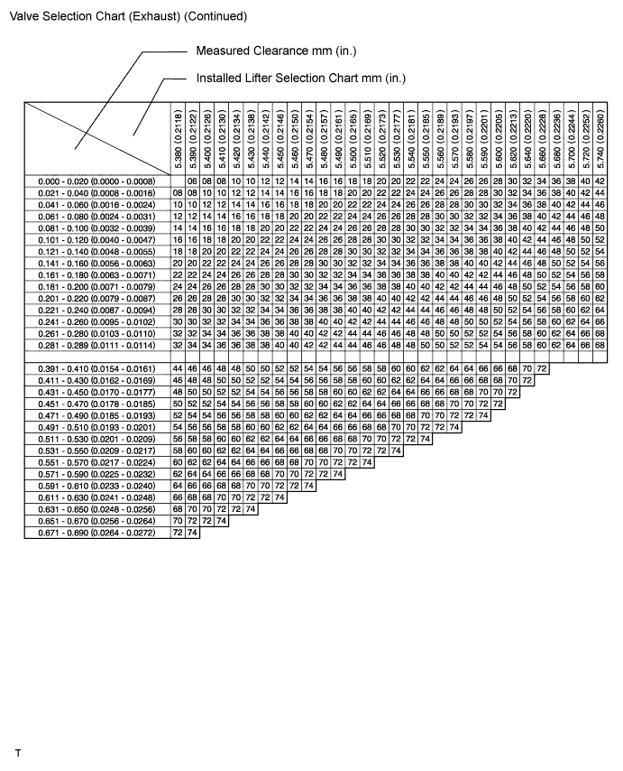
| No. | Thickness | No. | Thickness | No. | Thickness |
| 06 | 5.060 (0.1992) | 30 | 5.300 (0.2087) | 54 | 5.540 (0.2181) |
| 08 | 5.080 (0.2000) | 32 | 5.320 (0.2094) | 56 | 5.560 (0.2189) |
| 10 | 5.100 (0.2008) | 34 | 5.340 (0.2102) | 58 | 5.580 (0.2197) |
| 12 | 5.120 (0.2016) | 36 | 5.360 (0.2110) | 60 | 5.600 (0.2205) |
| 14 | 5.140 (0.2024) | 38 | 5.380 (0.2118) | 62 | 5.620 (0.2213) |
| 16 | 5.160 (0.2031) | 40 | 5.400 (0.2126) | 64 | 5.640 (0.2220) |
| 18 | 5.180 (0.2039) | 42 | 5.420 (0.2134) | 66 | 5.660 (0.2189) |
| 20 | 5.200 (0.2047) | 44 | 5.440 (0.2142) | 68 | 5.680 (0.2236) |
| 22 | 5.220 (0.2055) | 46 | 5.460 (0.2150) | 70 | 5.700 (0.2244) |
| 24 | 5.240 (0.2063) | 48 | 5.480 (0.2157) | 72 | 5.720 (0.2252) |
| 26 | 5.260 (0.2071) | 50 | 5.500 (0.2165) | 74 | 5.740 (0.2260) |
| 28 | 5.280 (0.2079) | 52 | 5.520 (0.2173) |
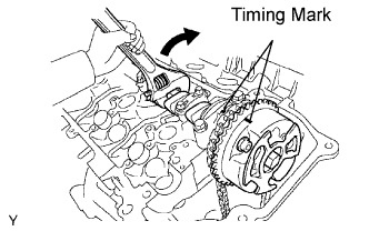
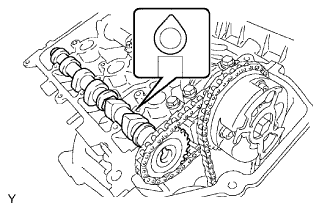
Install the No. 3 camshaft.
|
Align the mark link (yellow) with the timing mark (2 dot marks) of the camshaft timing gear as shown in the illustration.
Apply new engine oil to the thrust portion and journal of the camshafts.
 |
Temporarily put the No. 1 chain on the No. 2 chain of the camshaft timing gear.
|
Set the No. 3 camshaft onto the LH cylinder head with the cam lobes of the No. 2 cylinder faces downward as shown in the illustration.
|
Install the 4 bearing caps in their proper locations.
Apply a light coat of engine oil on the threads of the bearing cap bolts.
|
Install the 8 bearing cap bolts. Using several steps, tighten the bolts uniformly in the sequence as shown in the illustration.
|
Set the paint mark of the No. 1 chain between the timing marks of the camshaft timing gear.
|
Install the No. 3 chain tensioner.
While pushing in the tensioner, insert a diameter 1.0 mm (0.039 in.) pin into the hole to hold to fix it in place.
|
Temporarily install the camshaft timing gear and No. 3 chain tensioner and align the mark links (yellow) with the timing marks (1 dot mark and 2 dot marks) of the camshaft timing gears.
Tighten the No. 3 chain tensioner bolt.
Install the No. 4 camshaft sub-assembly.
|
Align the knock pin hole in the camshaft timing gear with the knock pin of the No. 4 camshaft, and insert the No. 4 camshaft into the camshaft timing gear.
Temporarily install the camshaft timing gear set bolt.
|
Install the 4 bearing caps in their proper locations.
Apply a light coat of engine oil on the threads and under the heads of the bearing cap bolts.
|
Install the 8 bearing cap bolts. Using several steps, tighten the bolts uniformly in the sequence as shown in the illustration.
 |
Hold the hexagonal portion of the No. 4 camshaft with a wrench, and tighten the camshaft timing gear set bolt.
Remove the pin from the No. 3 chain tensioner.
Install the camshaft.
 |
Align the mark link (yellow) with the timing mark (1 dot mark) of the camshaft timing gear as shown in the illustration.
Apply new engine oil to the thrust portion and journal of the camshafts.
 |
Temporarily put the No. 1 chain on the No. 2 chain of the camshaft timing gear.
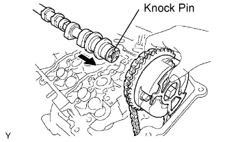 |
Align the knock pin hole in the camshaft timing gear with the knock pin of the No. 1 camshaft, and insert the No. 1 camshaft into the camshaft timing gear.
Temporarily install the camshaft timing gear set bolt.
 |
Set the No. 1 camshaft onto the RH cylinder head with the cam lobes of the No. 1 cylinder faces downward as shown in the illustration.
 |
Install the 4 bearing caps in their proper locations.
Apply a light coat of engine oil on the threads and under the heads of the bearing cap bolts.
 |
Install the 8 bearing cap bolts. Using several steps, tighten the bolts uniformly in the sequence as shown in the illustration.
 |
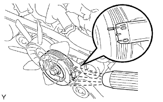
Rotate the No. 1 camshaft clockwise using hexagonal portion of the No. 1 camshaft so that the timing mark of the camshaft timing gear is aligned with the timing marks of the camshaft bearing cap.
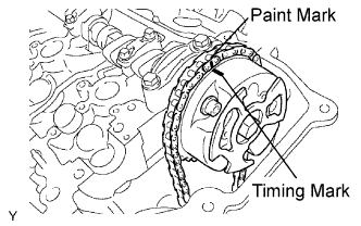 |
Align the paint mark of the No. 1 chain with the timing mark of the camshaft timing gear.
|
Hold the hexagonal portion of the No. 1 camshaft with a wrench, and tighten the camshaft timing gear set bolt.
 |
Install the No. 2 chain tensioner.
While pushing in the tensioner, insert a diameter of 1.0 mm (0.039 in.) pin into the hole to fix it in place.
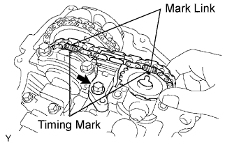 |
Temporarily install the camshaft timing gear and No. 2 chain tensioner and align the mark links (yellow) with the timing marks (1 dot mark) of the camshaft timing gears.
Tighten the chain tensioner No. 2 bolt.
Install the No. 2 camshaft.
 |
Set the No. 2 camshaft onto the RH cylinder head with the cam lobes of No. 1 cylinder faces upward as shown in the illustration.
 |
Install the 4 bearing caps in their proper locations.
Apply a light coat of engine oil on the threads and under the heads of the bearing cap bolts.
 |
Install the 8 bearing cap bolts. Using several steps, tighten the bolts uniformly in the sequence as shown in the illustration.
 |
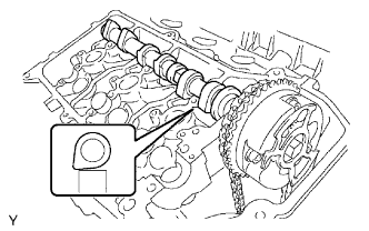
Rotate the No. 2 camshaft clockwise using the wrench so that the knock pin of the No. 2 camshaft is aligned with the knock pin hole of the camshaft timing gear.
 |
Hold the hexagonal portion of the No. 2 camshaft with a wrench, and install the camshaft timing gear set bolt.
Remove the pin from the No. 2 chain tensioner.
|
Install the No. 1 chain tensioner.
While turning the stopper plate of the tensioner clockwise, push in the plunger of the tensioner as shown in the illustration.
While turning the stopper plate of the tensioner counterclockwise, insert a bar of diameter of 3.5 mm (0.138 in.) into the holes in the stopper plate and tensioner to fix the stopper plate.
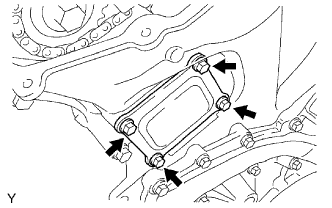
Install the chain tensioner with the 2 bolts.
Remove the bar from the chain tensioner.
Install a new gasket and the timing chain cover plate with the 4 bolts.
|
Slowly turn the crankshaft pulley 2 complete revolutions, and align the notch with timing mark 0 of the timing chain cover.
|
Check that the timing marks of the camshaft timing gears are aligned with the timing marks of the bearing cap as shown in the illustration.
| 8. INSTALL CYLINDER HEAD COVER LH |
Remove any old packing (FIPG) material and be careful not to drop any oil on the contact surfaces of the cylinder head, timing chain cover and cylinder head cover.
Apply adhesive on the threads of the ventilation valve.
Install the ventilation valve to the cylinder head cover.
Install the gasket to the cylinder head cover.
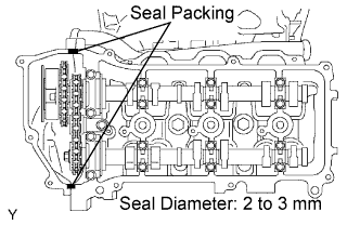 |
Apply a continuous bead of the seal packing to the cylinder head and timing chain cover as shown in the illustration.
Install the seal washers to the bolts.
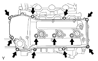 |
Install the cylinder head cover with the 10 bolts and 2 nuts. Uniformly tighten the bolts and nuts in several passes.
| 9. INSTALL CYLINDER HEAD COVER RH |
Remove any old packing (FIPG) material and be careful not to drop any oil on the contact surfaces of the cylinder head, timing chain cover and cylinder head cover.
Install the gasket to the cylinder head cover.
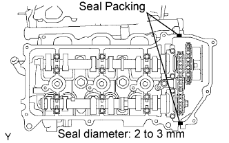 |
Apply a continuous bead of the seal packing to the cylinder head and timing chain cover as shown in the illustration.
Install the seal washers to the bolts.
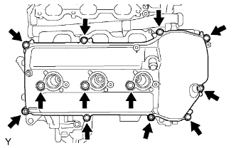 |
Install the cylinder head cover with the 10 bolts and 2 nuts. Uniformly tighten the bolts and nuts in several passes.
| 10. INSTALL IGNITION COIL |
| 11. INSTALL INTAKE AIR SURGE TANK |
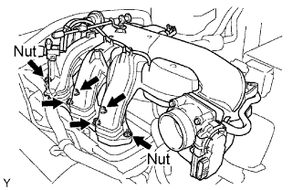 |
Install a new gasket to the intake air surge tank.
Using an 8 mm socket hexagon wrench, install the intake air surge tank with the 4 bolts and 2 nuts.
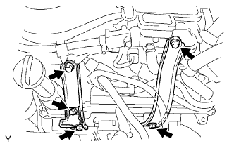 |
Install the 2 surge tank stays with the 4 bolts.
Install the oil baffle plate with the bolt.
 |
Install the throttle body bracket with the 2 bolts.
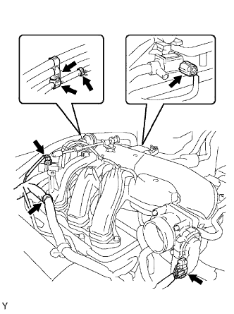
Install the 3 wire harness clamps and hose clamp.
Connect the throttle body with motor connector.
Connect the 2 VSV connectors.
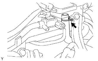 |
Connect the ventilation hose.
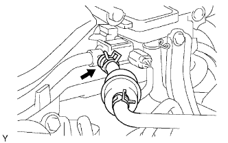 |
Connect the fuel vapor feed hose.
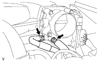 |
Connect the 2 water by-pass hoses.
| 12. REMOVE AIR CLEANER |
| 13. CONNECT NO. 2 VENTILATION HOSE |
| 14. CONNECT CABLE TO BATTERY NEGATIVE TERMINAL |
| 15. PERFORM INITIALIZATION |
Perform initialization (Click here).
| 16. ADD ENGINE COOLANT |
Tighten all the plugs and fill the radiator with TOYOTA Super Long Life Coolant (SLLC).
| Item | Specified Condition |
| A/T | 9.8 liters (10.4 US qts, 8.6 lmp. qts) |
| M/T | 8.5 liters (9.0 US qts, 7.5 lmp. qts) |
Press the inlet and outlet radiator hoses several times by hand, and then check the level of the coolant.
Install the radiator cap.
Bleed air from the cooling system.
Warm up the engine until the thermostat opens. While the thermostat is open, circulate the coolant for several minutes.
Maintain the engine speed at 2,000 to 2,500 rpm.
Press the inlet and outlet radiator hoses several times by hand to bleed air.
Stop the engine and wait until the coolant cools down to ambient temperature.
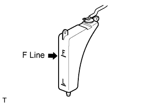 |
Check the coolant level in the radiator reservoir.
If the coolant level is low, add SLLC to the reservoir F line.
| 17. CHECK FOR ENGINE COOLANT LEAKS |
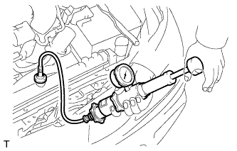 |
Fill the radiator with coolant and attach a radiator cap tester.
Warm up the engine.
Using the radiator cap tester, increase the pressure inside the radiator to 118 kPa (1.2 kgf/cm2, 17.1 psi), and check that the pressure does not drop.
If the pressure drops, check the hoses, radiator and water pump for leaks. If no external leaks are found, check the cylinder block and head.
| 18. INSTALL V-BANK COVER |
Install the V-bank cover with the 2 nuts.
| 19. INSPECT IGNITION TIMING |
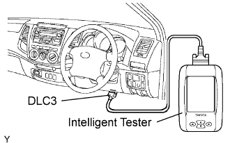 |
When using intelligent tester:
Check the ignition timing.
Connect the intelligent tester to the DLC3.
Disconnect the intelligent tester from the DLC3.
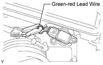 |
When not using intelligent tester.
Check the ignition timing.
Remove the air cleaner cap.
Connect the tester probe of a timing light to the green-red read wire of the ignition coil connector for the No.1 cylinder.
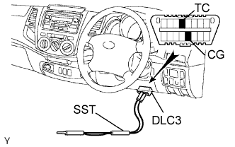 |
Using SST, connect terminals TC and CG of the DLC3.
 |
Using the timing light, check the ignition timing.
Remove the SST from the DLC3.
Check the ignition timing.
Disconnect the timing light from the engine.
Install the air cleaner cap.
