OIL PUMP > REMOVAL |
| 1. DISCHARGE FUEL SYSTEM PRESSURE |
Disconnect the cable from the negative (-) battery terminal.
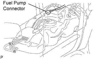 |
Disconnect the fuel pump connector.
Connect the cable to the negative (-) battery terminal.
Start the engine. After the engine has stopped on its own, turn the ignition switch OFF.
Crank the engine again, then check that the engine does not start.
Loosen the fuel tank cap, then discharge the pressure in the fuel tank completely.
Connect the fuel pump connector.
| 2. DISCONNECT CABLE FROM NEGATIVE BATTERY TERMINAL |
| 3. REMOVE ENGINE ASSEMBLY |
Remove the engine from the vehicle (Click here).
| 4. INSTALL ENGINE TO STAND |
Place the engine onto the stand.
| 5. REMOVE IGNITION COIL |
Remove the bolt and ignition coil.
| 6. REMOVE SPARK PLUG |
| 7. REMOVE THROTTLE BODY |
Disconnect the throttle control motor & throttle position sensor connector.
Disconnect the 2 water by-pass hoses.
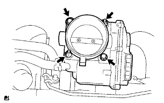 |
Remove the 2 bolts, 2 nuts and throttle body.
Remove the gasket.
| 8. REMOVE INTAKE MANIFOLD |
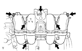 |
Disconnect the crankshaft position sensor from the clamp.
Remove the 5 bolts, 2 nuts, intake manifold and gasket.
| 9. REMOVE GENERATOR |
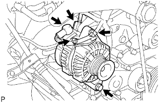 |
Remove the nut, bolt and generator wire.
Disconnect the generator connector.
Remove the 2 bolts and generator.
| 10. REMOVE COMPRESSOR MOUNTING BRACKET |
 |
Remove the 5 bolts and compressor mounting bracket.
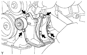
| 11. REMOVE V-RIBBED BELT TENSIONER |
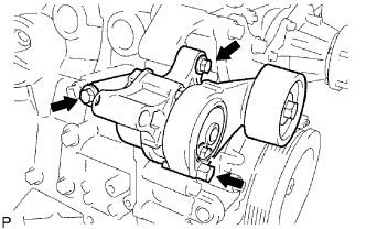 |
Remove the 3 bolts and belt tensioner.
| 12. REMOVE WATER INLET |
Remove the bolt, 2 nuts, water inlet and gasket.
| 13. REMOVE THERMOSTAT |
Remove the thermostat and gasket.
| 14. REMOVE IDLER PULLEY |
Remove the bolt, pulley plate, idler pulley and spacer.
| 15. REMOVE NO. 1 WATER BY-PASS PIPE |
Remove the 2 nuts, water by-pass pipe and gasket.
| 16. REMOVE OIL FILLER CAP |
| 17. REMOVE CYLINDER HEAD COVER |
Remove the 19 bolts, 2 nuts, head cover and 2 gaskets.
| 18. REMOVE CAMSHAFT POSITION SENSOR |
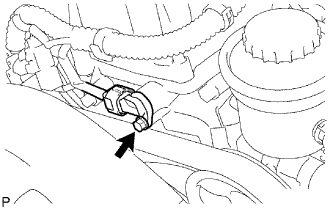 |
Disconnect the sensor connector.
Remove the bolt and sensor.
| 19. REMOVE CRANKSHAFT PULLEY |
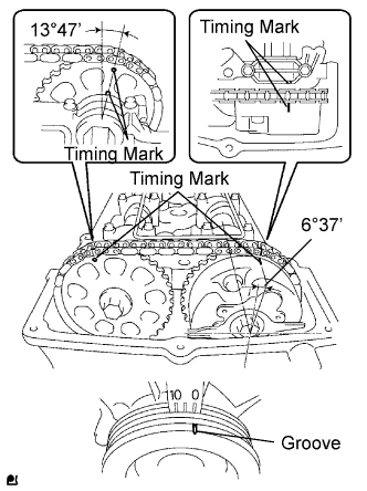 |
Turn the crankshaft pulley, and align its groove with timing mark 0 of the timing chain cover.
Check that the timing marks of the camshaft timing gear and sprocket are aligned with the timing marks of the No. 1 bearing cap, as shown in the illustration.
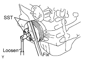 |
Using SST, loosen the pulley bolt.
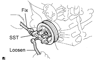 |
Using SST, remove the pulley bolt and pulley.
| 20. REMOVE NO. 2 OIL PAN |
 |
Remove the drain plug and gasket.
Remove the 20 bolts and 2 nuts.
Insert the blade of SST between the oil pans. Cut through the applied sealer and remove the oil pan.
| 21. REMOVE OIL STRAINER |
Remove the bolt, 2 nuts, oil strainer and gasket.
| 22. REMOVE NO. 1 OIL PAN |
 |
Remove the 16 bolts and 2 nuts.
Remove the oil pan by prying between the oil pan and cylinder block with a screwdriver.
Remove the O-ring.
| 23. REMOVE CRANKSHAFT POSITION SENSOR |
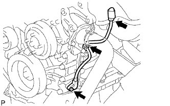 |
Disconnect the sensor connector.
Disconnect the connector from the connector bracket.
Detach the harness clamp.
Remove the bolt and sensor.
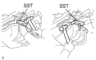
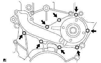
| 24. REMOVE TIMING CHAIN COVER (OIL PUMP ASSEMBLY) |
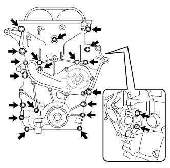 |
Remove the 19 bolts and 2 nuts shown in the illustration.
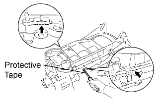
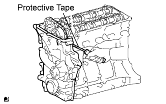 |
Remove the timing chain cover by prying between the timing chain cover and cylinder head or cylinder block with a screwdriver.
Remove the 3 O-rings.
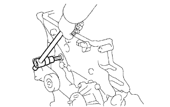 |
Using a 10 mm socket hexagon wrench, remove the timing gear case plug.
| 25. REMOVE WATER PUMP |
 |
Remove the 8 bolts, water pump and gasket.
