OIL PUMP > INSPECTION |
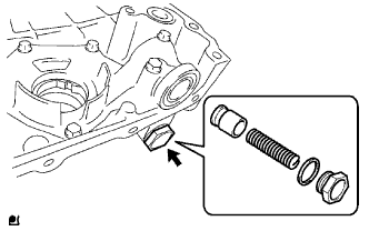
| 1. REMOVE OIL PUMP RELIEF VALVE |
 |
Using a 27 mm socket wrench, remove the plug and gasket.
Remove the valve spring and relief valve.
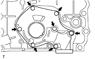
| 2. REMOVE OIL PUMP COVER |
Remove the 7 bolts and oil pump cover.
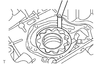
| 3. REMOVE OIL PUMP ROTOR SET |
 |
Remove the oil pump rotor set from the timing chain cover.
| 4. INSPECT OIL PUMP RELIEF VALVE |
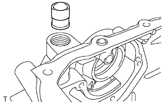 |
Coat the relief valve with engine oil and drop it into the relief valve hole.
Check that the relief valve falls in smoothly by its own weight.
If it does not, replace the relief valve. If necessary, replace the timing chain cover.
| 5. INSPECT OIL PUMP ROTOR SET |
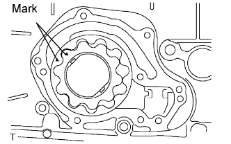 |
Install the rotors to the oil pump body with the rotors' marks facing outward. Check that the rotors revolve smoothly.
Check the tip clearance.
Using a feeler gauge, measure the clearance between the drive and driven rotor tips, as shown in the illustration.
| Condition | Clearance |
| Standard | 0.040 to 0.160 mm (0.0016 to 0.0063 in.) |
| Maximum | 0.26 mm (0.0102 in.) |
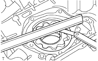 |
Check the side clearance.
Using a feeler gauge and precision straightedge, measure the clearance between the rotors and precision straightedge, as shown in the illustration.
| Condition | Clearance |
| Standard | 0.025 to 0.075 mm (0.0010 to 0.0030 in.) |
| Maximum | 0.130 mm (0.0051 in.) |
 |
Check the body clearance.
Using a feeler gauge, measure the clearance between the oil pump body and driven rotor, as shown in the illustration.
| Condition | Clearance |
| Standard | 0.025 to 0.325 mm (0.0010 to 0.0128 in.) |
| Maximum | 0.425 mm (0.0167 in.) |
| 6. INSTALL OIL PUMP ROTOR SET |
|
Coat the oil pump gear set with engine oil and place it into pump body with the marks facing outward (pump body cover side). Check that the rotors revolve smoothly.
| 7. INSTALL OIL PUMP COVER |
|
Install the oil pump cover with the 7 bolts.
| 8. INSTALL OIL PUMP RELIEF VALVE |
 |
Coat the relief valve with engine oil.
Insert the relief valve and spring into the pump body hole.
Install a new gasket to the plug.
Using a 27 mm socket wrench, install the plug.
