OIL PUMP > INSTALLATION |
| 1. INSTALL WATER PUMP |
 |
Install a new gasket and the water pump with the 8 bolts.
| 2. INSTALL TIMING CHAIN COVER |
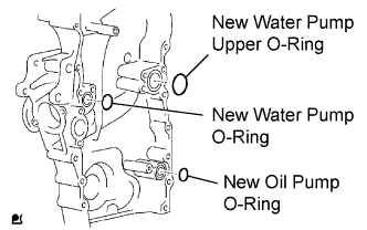 |
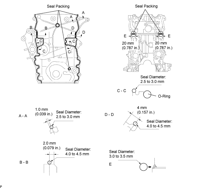
Install 3 new O-rings to the timing chain cover as shown in the illustration.
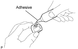 |
Apply adhesive to the timing gear case plug.
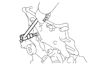 |
Using a 10 mm socket hexagon wrench, install the timing gear case plug.
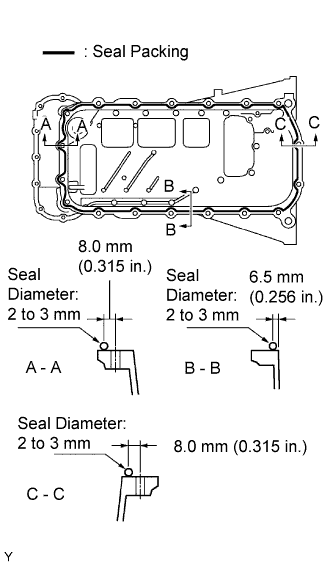
Apply seal packing in a continuous line as shown in the illustration.
| Position | Specified Condition |
| A - A, C - C | 2.5 to 3.0 mm (0.098 to 0.118 in.) |
| B - B, D - D | 4.0 to 4.5 mm (0.157 to 0.177 in.) |
| E | 3.0 to 3.5 mm (0.118 to 0.138 in.) |
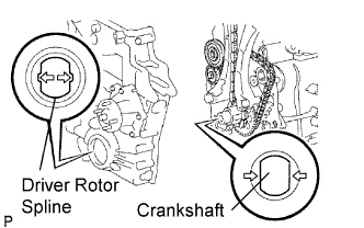 |
Align the oil pump's drive rotor spline and crankshaft as shown in the illustration. Install the spline and chain cover plate to the crankshaft.
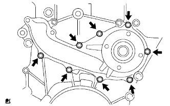
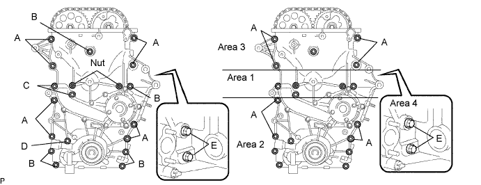
Temporarily install the timing chain cover with the 19 bolts and 2 nuts.
Excluding bolt A, tighten the bolts and nuts in this order: Area 1, Area 2, Area 3.
Tighten the bolts labeled A in this order: Area 2 and Area 3.
Tighten the bolts labeled E for Area 4.
| 3. INSTALL CRANKSHAFT POSITION SENSOR |
 |
Apply a light coat of engine oil to the O-ring of the sensor.
Install the sensor with the bolt.
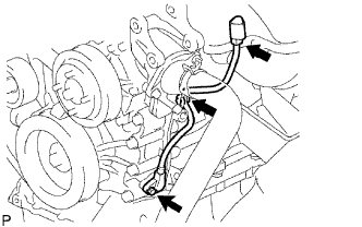
Install the connector to the connector bracket.
Attach the harness clamp.
Connect the sensor connector.
| 4. INSTALL NO. 1 OIL PAN |
 |
Apply seal packing in a continuous line as shown in the illustration.
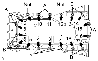 |
Temporarily install the oil pan with the 16 bolts and 2 nuts.
Uniformly tighten the 16 bolts and 2 nuts in the order shown in the illustration.
| 5. INSTALL OIL STRAINER |
Install a new gasket and the oil strainer with the bolt and 2 nuts.
| 6. INSTALL NO. 2 OIL PAN |
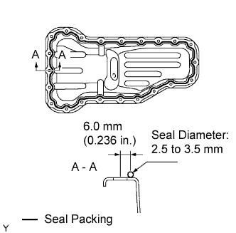 |
Apply seal packing in a continuous line as shown in the illustration.
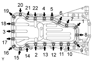 |
Temporarily install the oil pan with the 20 bolts and 2 nuts.
Uniformly tighten the 20 bolts and 2 nuts in the order shown in the illustration.
Install a new gasket and the drain plug.
| 7. INSTALL CRANKSHAFT PULLEY |
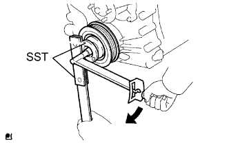 |
Align the pulley set key with the key groove of the pulley, and slide on the pulley.
Using SST, install the crankshaft pulley bolt.
| 8. INSTALL CAMSHAFT POSITION SENSOR |
Apply a coat of engine oil to a new O-ring.
Install the sensor with the bolt.
| 9. INSTALL CYLINDER HEAD COVER |
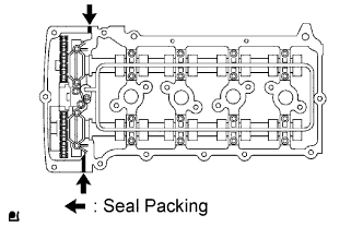 |
Install the 2 cover gaskets to the head cover.
Apply seal packing to the places shown in the illustration.
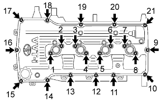 |
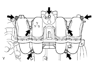
Temporarily install the head cover with the 19 bolts and 2 nuts.
Uniformly tighten the 19 bolts and 2 nuts in the order shown in the illustration.
In numerical order, confirm that the bolts labeled 1 to 8 are tightened to the torque specification. Tighten the bolts as necessary.
| 10. INSTALL OIL FILLER CAP |
| 11. INSTALL NO. 1 WATER BY-PASS PIPE |
Install a new gasket and the water by-pass pipe with the 2 nuts.
| 12. INSTALL NO. 1 IDLER PULLEY |
Install the spacer, idler pulley and pulley plate with the bolt.
| 13. INSTALL V-RIBBED BELT TENSIONER |
 |
Temporarily install the belt tensioner with the 3 bolts.
Install the tensioner by tightening the 3 bolts in the order shown in the illustration.
| 14. INSTALL THERMOSTAT |
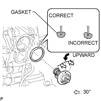 |
Install a new gasket to the thermostat.
Insert the thermostat into the cylinder block with the jiggle valve facing straight upward.
| 15. INSTALL WATER INLET |
Install the inlet with the 2 nuts and bolt.
Connect the connector.
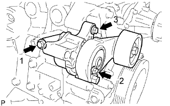
| 16. INSTALL COMPRESSOR MOUNTING BRACKET (w/ Air Conditioning) |
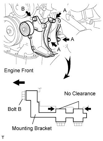 |
Temporarily install the mounting bracket with the 3 bolts labeled A.
Make sure there is no clearance between the cylinder block and bracket as shown in the illustration. Then install the bolt labeled B.
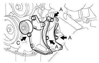 |
Tighten the bolts labeled A and install the bolt labeled C.
| 17. INSTALL GENERATOR |
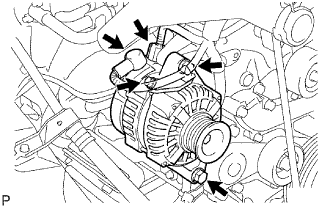 |
Install the generator with the 2 bolts.
Install the generator wire with the bolt and nut.
Connect the connector.
| 18. INSTALL INTAKE MANIFOLD |
 |
Install a new gasket and the intake manifold with the 5 bolts and 2 nuts.
Connect the crankshaft position sensor to the clamp.
| 19. INSTALL THROTTLE BODY |
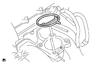 |
Install a new gasket on the intake manifold.
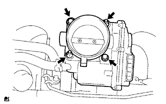 |
Install the throttle body with the 2 bolts and 2 nuts.
Connect the water by-pass hose to the throttle body.
Connector the throttle control motor & throttle position sensor connector.
| 20. INSTALL SPARK PLUG |
| 21. INSTALL IGNITION COIL |
Install the ignition coil with the bolt.
| 22. REMOVE ENGINE ASSEMBLY FROM ENGINE STAND |
| 23. INSTALL ENGINE ASSEMBLY |
Install the engine to the vehicle (Click here).
| 24. CONNECT CABLE TO NEGATIVE BATTERY TERMINAL |
| 25. ADD ENGINE OIL |
Clean and install the oil drain plug with a new gasket.
Add fresh engine oil.
| Item | Capacity |
| Drain and refill with oil filter change | 5.6 liters (5.9 US qts, 4.9 lmp. qts) |
| Drain and refill without oil filter change | 5.3 liters (5.6 US qts, 4.6 lmp. qts) |
| Dry fill | 6.3 liters (6.7 US qts, 5.5 lmp. qts) |
Install the oil filler cap.
| 26. ADD ENGINE COOLANT |
Tighten all the plugs and fill the radiator with TOYOTA Super Long Life Coolant (SLLC).
| Item | Specified Capacity |
| A/T | 7.3 liters (7.7 US qts, 6.4 lmp. qts) |
| M/T | 7.0 liters (7.4 US qts, 6.2 lmp. qts) |
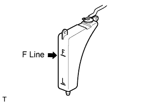
Fill the radiator with TOYOTA Super Long Life Coolant (SLLC) to the F line.
Press the inlet and outlet radiator hoses several times by hand, and then check the level of the coolant.
If the coolant level drops below the F line, add TOYOTA SLLC to the F line.
Install the radiator cap.
Bleed air from the cooling system.
Warm up the engine until the thermostat opens. While the thermostat is open, circulate the coolant for several minutes.
Maintain the engine speed at 2,000 to 2,500 rpm.
Press the inlet and outlet radiator hoses several times by hand to bleed air.
Stop the engine and wait until the coolant cools down to ambient temperature.
 |
Check the coolant level in the radiator reservoir.
If the coolant level is low, add SLLC to the reservoir F line.
| 27. CHECK FUEL FOR LEAKS |
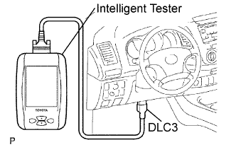
Connect the intelligent tester to the DLC3.
Turn the ignition switch ON.
Push the intelligent tester main switch ON.
Select the Active Test and enter the following menus: Powertrain / Engine and ECT / Active Test / Control the Fuel Pump / Speed.
Check for fuel leaks.
Check that there are no fuel leaks after performing maintenance anywhere on the fuel system.
| 28. CHECK FOR OIL LEAKS |
Start the engine, and check that there are no oil leaks after performing maintenance.
| 29. CHECK FOR COOLANT LEAKS |
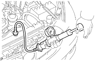 |
Fill the radiator with coolant and attach a radiator cap tester.
Warm up the engine.
Using the radiator cap tester, increase the pressure inside the radiator to 118 kPa (1.2 kgf/cm2, 17.1 psi), and check that the pressure does not drop.
If the pressure drops, check the hoses, radiator and water pump for leaks. If no external leaks are found, check the cylinder block and head.
| 30. CHECK IDLE SPEED AND IGNITION TIMING |
Warm up and stop the engine.
Check the idle speed control system.
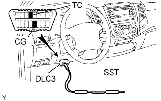 |
Using SST, connect terminals TC and CG of the DLC3.
Start the engine at idle.
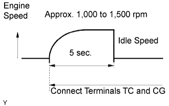 |
After connecting terminals (TC and CG), check that the engine speed changes to approximately 1,000 to 1,500 rpm for 5 seconds, and then returns to idle speed.
If the result is not as specified, check the throttle body, DTC (Click here) and wire harness.
| 31. CHECK CO (for Leaded Gasoline Specification Vehicle) |
Initial condition:
Engine at normal operating temperature
Air cleaner installed
All pipes and hoses of air induction system connected
All accessories switched OFF
All vacuum lines properly connected
SFI system wiring connectors fully seated
Ignition timing set correctly
Transmission in neutral position
Tachometer and CO meter calibration at idle
Warm up the engine under constant speed (approximately 50 km/h (31 mph)). Close the throttle valve for 5 minutes after the engine coolant temperature becomes stable (80 to 90°C (176 to 194°F)) and idle the engine for 5 minutes.
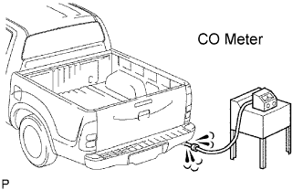 |
Insert a tester probe at least 40 cm (1.3 ft.) into the tailpipe.
Wait at least 1 minute before measuring to allow the concentration to stabilize. Complete the measuring within 3 minutes.
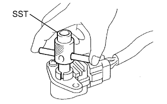 |
If the CO concentration does not conform to regulations, adjust by turning the idle mixture adjusting screw in the variable resistor with SST.
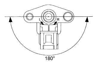 |
The idle mixture adjusting screw can be adjusted through an 180° angle range.
If the CO concentration is within specification, this adjustment is complete.
If the CO concentration cannot be corrected by idle mixture adjustment, see the table below for other possible causes.
| CO | Problems | Causes |
| High | Rough idle (black smoke from exhaust) |
|
| 32. CHECK CO/HC (for Unleaded Gasoline Specification Vehicle) |
Start and warm up the engine.
Run the engine at 2,500 rpm for approximately 180 seconds and idle the engine.
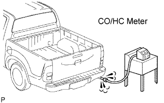 |
Insert CO/HC meter testing probe at least 40 cm (1.3 ft.) into the tailpipe.
Check CO/HC concentration at idle.
If the CO/HC concentration is not as specified, perform troubleshooting in the order given below.
Check the heated oxygen sensor operation (Click here).
See the table below for possible causes, and then inspect and repair the applicable causes if necessary.
| CO | HC | Problems | Causes |
| Normal | High | Rough idle |
|
| Low | High | Rough idle (Fluctuating HC reading) |
|
| High | High | Rough idle (Black smoke from exhaust) |
|
| 33. CHECK FUNCTION OF THROTTLE BODY |
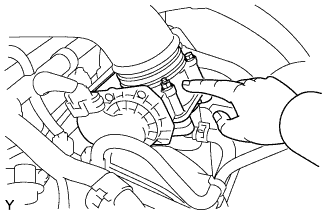 |
Check the throttle control motor operating sound.
Turn the ignition switch ON.
When pressing the accelerator pedal, check the operating sound of the running motor. Make sure that no friction noises emit from the motor.
If friction noise is heard, replace the throttle body.
 |
Check the throttle position sensor.
Connect the intelligent tester to the DLC3.
Turn the ignition switch ON.
Under Current Data, check that the throttle valve opening percentage (Throttle Pos) is within the standard.
| 34. PERFORM INITIALIZATION |
Perform initialization (Click here).
